|
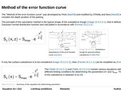
The "Method of the error function curve" was developed by Peck [Mair93] and modified by O'Reilly and New [New92] in order to also consider the depth position of the jacking. The principle of the calculation method is the typical shape of the subsidence trough (Bild 15.2.1.1), that is defined by the Gaussian normal distribution function and calculated in accordance with Formel 15.2.1.1 : (Formula: Error Function Curve)
|
(Image: Depth dependency of the … |
|
|
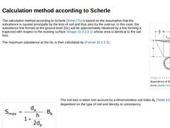
(Image: Depth dependency of the error function curve [Scher77c]) The calculation method according to Scherle [Scher77c] is based on the assumption that the subsidence is caused principally by the loss of soil and thus also by the overcut. In this case, the subsidence line formed at the ground level (GL) will be approximately idealized by a line forming a trapezoid with respect to the existing surface (Bild 15.2.1.2) whose area is identical to the … |
|
|
|
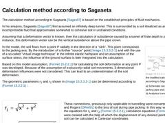
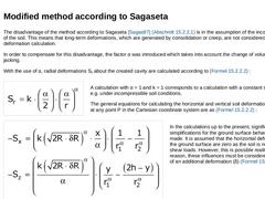
The calculation method according to Sagaseta [Sagas87] is based on the established principles of fluid mechanics. In his analysis, Sagaseta [Sagas87] first assumed an infinitely deep tunnel. This is surrounded by a soil idealized as an incompressible fluid that approximates somewhat to cohesive soil in undrained conditions. Assuming that a deformation vector is known, then the calculation of subsidence caused by a tunnel of finite depth is possible. … |
|
The disadvantage of the method according to Sagaseta [Sagas87] (Abschnitt 15.2.2.1) is in the assumption of the incompressibility of the soil. This means that long-term deformations, which are generated by consolidation or creep, are not considered in the deformation calculation. In order to compensate for this disadvantage, the factor α was introduced which takes into account the change of volume during pipe jacking. With the use of α, radial deformations … |

|
|
|
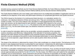
Included among numerical methods are the Finite Element Method (FEM), the Finite Difference Method (FDM), the Kinematic Element Method (KEM), the Boundary Element Method (BEM) and the Discrete Element Method (DEM). The Finite Element Method is the most widely used method due to its multifaceted possibilities of application and its particular suitability for the depiction of the stress and deformation behaviour of complicated geometries and spatial … |
|
|
|
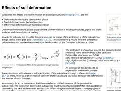
(Image: Effects of soil deformation on adjoining structures [Attew86]) Critical for the effects of soil deformation on existing structures (Bild 15.3) are the - Deformations during the construction phase
- Total deformations in the final condition
- Differential deformations in the final condition
Differential deformations cause displacement or deformation at existing structures, pipes and traffic surfaces and thus additional loading. In order to estimate … |
|
|
|

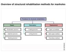
| (Image: Overview of the main processing groups for the structural rehabilitation of drain and sewer systems)
|
|

|

|
|

|
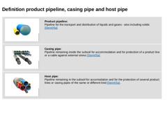
(Image: Product pipes [FI-Steina])
Product pipeline:
Pipeline for the transport and distribution of liquids and gases - also including solids [Stein05a]. |
|
(Image: Casing pipes [FI-Steina])
Casing pipe:
Pipeline remaining inside the subsoil for accommodation and for protection of a product line or a cable against external stress [Stein05a]. |
|
(Image: Bundled installation inside the host pipe [FI-Steina])
Host pipe:
Pipeline remaining in the subsoil … |
|
|

|
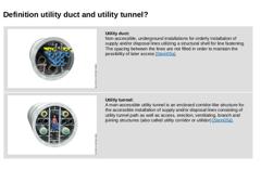
(Image: Utility duct)
Utility duct:
Non-accessible, underground installations for orderly installation of supply and/or disposal lines utilizing a structural shell for line fastening. The spacing between the lines are not filled in order to maintain the possibility of later access [Stein05a]. |
|
(Image: Man-accessible utility tunnel [FI-Steina])
Utility tunnel:
A man-accessible utility tunnel is an enclosed corridor-like structure for the accessible … |
|
|
|
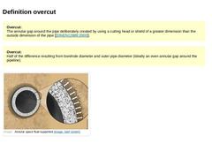
Overcut:
The annular gap around the pipe deliberately created by using a cutting head or shield of a greater dimension than the outside dimension of the pipe [ [DINEN12889:2000]]. |
|
|
|
Overcut:
Half of the difference resulting from borehole diameter and outer pipe diameter (ideally an even annular gap around the pipeline). |
|
|
|
(Image: Annular space fluid supported) |
|
|
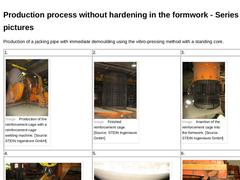
Production of a jacking pipe with immediate demoulding using the vibro-pressing method with a standing core. |
1. |
2. |
3. |
|
(Image: Production of the reinforcement cage with a reinforcement cage welding machine [STEIN Ingenieure GmbH]) |
(Image: Finished reinforcement cage) |
(Image: Insertion of the reinforcement cage into the formwork) |
|
4. |
5. |
6. |
|
(Image: Installation of the formwork with reinforcement cage in the pipe making machine) |
(Image: Positioning … |
|