|
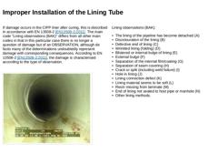
If damage occurs in the CIPP liner after curing, this is described in accordance with EN 13508-2 [EN13508-2:2011]. The main code "Lining observations (BAK)" differs from all other main codes in that in this particular case there is no longer a question of damage but of an OBSERVATION, although de facto many of the determinations undoubtedly represent damage with corresponding consequences. According to EN 13508-2 [EN13508-2:2011], the damage is characterised … |
|
Quality influences during installation are mainly caused by deviations in the process parameters to be observed (e.g. curing temperature and temperature profile, light intensity, inflation pressure, contact pressure, etc.). If the material parameters specified in the manufacturer's specifications or by initial or suitability testing are not achieved, the cause is often insufficient contact pressure of the lining tube against the host pipe wall or … |
|
|
|
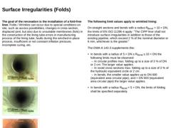
The goal of the renovation is the installation of a fold-free liner. Folds / Wrinkles can occur due to special conditions on site, such as access possibilities, changes in cross-section, displaced joint, but also due to unsuitable membranes (foils) in the construction of the lining tube errors, in manufacturing process of the lining tube, faults during the winched-in-place process, insufficient or not constant inflation pressure, incomplete curing, … |
|
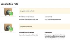
(Image: Lining observations – Longitudinal fold not filled) Longitudinal fold not filled Possible cause of damage Incorrectly manufactured lining tube Assessment CIPP liner statically weakened (Image: Lining observations – Longitudinal fold filled) Possible cause of damage Incorrectly manufactured lining tube Assessment The material properties in the fold must correspond to the properties of the ring, otherwise the CIPP liner is weakened |
|
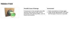
(Image: Lining observations – Hidden fold) Possible cause of damage Compression in the springline area after pressure drop during curing. Occurs particularly with special profiles, such as ovoid cross-sections Assessment -
Static assumptions no longer apply
-
Large annular gap between CIPP liner and host pipe of several cm possible
|
|
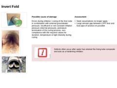
(Image: Lining observations – Invert fold) (Image: Lining observations - Invert fold in longitudinal direction) (Image: Lining observations – Invert fold) Possible cause of damage Errors during inflation / curing of the liner tube in combination with external groundwater pressure. Insufficient or non-constant inflation pressure (internal pressure), premature termination of the curing process, non-compliance with the required values for duration, temperature … |
|
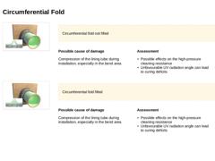
(Image: Lining observations – Circumferential fold not filled) Circumferential fold not filled Possible cause of damage Compression of the lining tube during installation, especially in the bend area Assessment -
Possible effects on the high-pressure cleaning resistance
-
Unfavourable UV radiation angle can lead to curing deficits
(Image: Lining observations – Circumferential fold filled) Circumferential fold filled Possible cause of damage Compression of … |
|
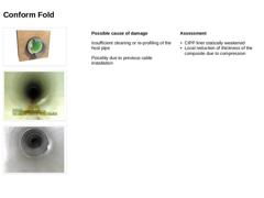
(Image: Lining observations – Conform fold) (Image: Lining observations – Conform fold) (Image: Lining observations – Conform fold) Possible cause of damage Insufficient cleaning or re-profiling of the host pipe Possibly due to previous cable installation Assessment -
CIPP liner statically weakened
-
Local reduction of thickness of the composite due to compression
|
|
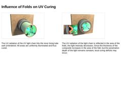
(Image: Influence of folds on UV curing - Without folds) The UV radiation of the UV light chain hits the inner lining tube wall unhindered. All areas are uniformly illuminated and thus cured. (Image: Influence of folds on UV curing – With folds) The UV radiation of the light chain is reflected in the area of the folds, the light intensity decreases. Since the thickness of the composite increases in the area of the fold, but the penetration depth of … |
|
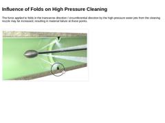
The force applied to folds in the transverse direction / circumferential direction by the high-pressure water jets from the cleaning nozzle may be increased, resulting in material failure at these points. (Image: Influence of folds on high pressure cleaning) |
|
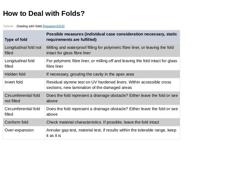
(Table: Dealing with folds [Haacker2015]) |
|
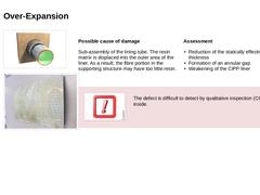
(Image: Lining observations – Over-expansion of the CIPP liner) (Image: Specimen from a GRP liner - resin matrix is displaced into the outer area of the CIPP liner) Possible cause of damage Sub-assembly of the lining tube. The resin matrix is displaced into the outer area of the liner. As a result, the fibre portion in the supporting structure may have too little resin. Assessment -
Reduction of the statically effective wall thickness
-
Formation of an …
|
|
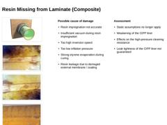
(Image: Lining observations – Resin missing from laminate) (Image: Resin missing from laminate (composite)) (Image: Resin missing from laminate (composite) - 4)
(Image: Resin missing from laminate (composite) - 2) (Image: Resin missing from laminate (composite) - 3) Possible cause of damage -
Resin impregnation not accurate
-
Insufficient vacuum during resin impregnation
-
Too high inversion speed
-
Too low inflation pressure
-
Strong styrene evaporation …
|
|
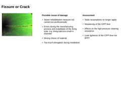
(Image: CIPP liner with longitudinal crack) Possible cause of damage -
Sewer rehabilitation measure not carried out professionally
-
Errors during the manufacturing process and installation of the lining tube, e.g. lining tube too small in diameter
-
Wrong choice of material
-
Too much elongation during installation
Assessment -
Static assumptions no longer apply
-
Weakening of the CIPP liner
-
Effects on the high pressure cleaning resistance
-
Leak tightness …
|
|
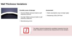
(Image: Wall thickness variations within the CIPP liner [MUNLV05]) Important: The defect cannot be detected by qualitative inspection from the inside. Detection is carried out by measurement on test samples. |
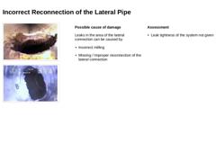
|
(Image: Incorrect reconnection of the lateral pipe - No leak tightness given) (Image: Incorrect reconnection of the lateral pipe - No leak tightness given) Possible cause of damage Leaks in the area of the lateral connection can be caused by Assessment -
Leak tightness of the system not given
|

|
|
|
The renovation of sewers and pipelines with "Lining with cured-in-place pipes" is an established standard construction method, starting with the planning process, through the production of materials and installation, right up to checking the quality achieved. It is characterised by a wide range of applications and a high variance in the fabrication and application processes. This module gives a detailed overview of the installation and curing processes in lining tube. Thus, this module creates the basis for an optimal process selection within the planning process and provides essential basic knowledge for construction supervision. This module requires knowledge of the module "Lining with cured-in-place pipes – Basics". After completing this module, you will have a sound knowledge of: - wall construction of the lining tube;
- possible uses and applications of CIPP liner;
- preparatory work, installation variants and the curing process;
- advantages and disadvantages of the various curing methods and requirements for structural verifications.
|

|
|
|
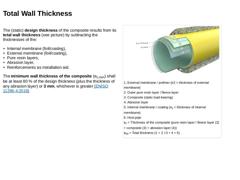
The (static) design thickness of the composite results from its total wall thickness (see picture) by subtracting the thicknesses of the: -
Internal membrane (foil/coating),
-
External membrane (foil/coating),
-
Pure resin layers,
-
Abrasion layer,
-
Reinforcements as installation aid.
The minimum wall thickness of the composite (ec,min) shall be at least 80 % of the design thickness (plus the thickness of any abrasion layer) or 3 mm, whichever is greater [… |
|
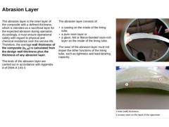
The abrasion layer is the inner layer of the composite with a defined thickness, which is intended as a sacrificial layer for the expected abrasion during operation. Accordingly, it must ensure operational safety with regard to physical and chemical resistance over the service life. Therefore, the average wall thickness of the composite (ec,m) is calculated from the design wall thickness plus the thickness of any abrasion layer. The tests of the abrasion … |
|
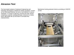
The Darmstadt Institute of Hydraulic Engineering and Hydrology developed a method for testing resistance. Known as the Darmstadt Method, the test is now defined in various standards. It consists of placing a semicircular pipe section containing a specific sand/gravel/water mixture on a rocker, which alternately tilts up and down to simulate flow characteristics. Mechanical rocking abrasion device according to CEN/TR 15729: (Image: Mechanical rocking … |
|
For the proof of suitability, all properties must be checked under consideration of the standards and regulations. These tests shall take into account, among other things -
Properties and description of the raw materials,
-
Structure of the hardened lining tube (CIPP product),
-
Stability (mechanical short and long term properties),
-
Operational characteristics (abrasion, HD flushing, chemical resistance),
-
Environmental compatibility.
Furthermore, a |
|
(Image: Picto Beratung) The application of lining with cured-in-place pipes requires a careful analysis and assessment of the stability of the host pipe-soil system. The structural stability of the object to be rehabilitated must allow the lining tube to be inserted. The hydraulic capacity must also be given after the rehabilitation of the drain / sewer cross section. The CIPP product design shall be in accordance with the requirements of ISO 11296-… |