|
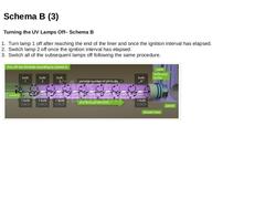
Turning the UV Lamps Off– Schema B
-
Turn lamp 1 off after reaching the end of the liner and once the ignition interval has elapsed.
-
Switch lamp 2 off once the ignition interval has elapsed.
-
Switch all of the subsequent lamps off following the same procedure.
(Image: Turning the UV Lamps Off – Schema B) |
|
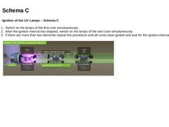
Ignition of the UV Lamps – Schema C
-
Switch on the lamps of the first core simultaneously.
-
After the ignition interval has elapsed, switch on the lamps of the next core simultaneously.
-
If there are more than two elements repeat this procedure until all cores have ignited and wait for the ignition interval to elapse.
(Image: Ignition of the UV lamps – Schema C ) |
|
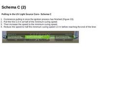
Pulling in the UV Light Source Core– Schema C
-
Commence pulling in once the ignition process has finished (Figure 33).
-
Pull the first 1.0 m at half of the minimum curing speed.
-
Then increase the speed to the minimum curing speed.
-
Reduce the speed to half the minimum curing speed 1.0 m before reaching the end of the liner.
(Image: Minimum pulling in speed - Schema C) |
|
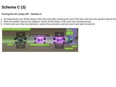
Turning the UV Lamps Off – Schema C
-
Simultaneously turn off the lamps of the first core after reaching the end of the liner and once the ignition interval has elapsed.
-
After the ignition interval has elapsed, switch off the lamps of the next core simultaneously.
-
If there are more than two elements, repeat this procedure until all cores have been turned off.
(Image: Turning the UV lamps off – Schema C) |
|
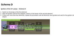
Ignition of the UV Lamps – Schema D -
Switch on the lamps of the first element.
-
After the ignition interval has elapsed, switch on the lamps of the second element.
-
If there are more than two elements, repeat this procedure until all elements have ignited and wait for the ignition interval to elapse.
(Image: Ignition of the UV lamps – Schema D) |
|
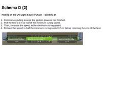
Pulling in the UV Light Source Chain – Schema D -
Commence pulling in once the ignition process has finished.
-
Pull the first 0.5 m at half of the minimum curing speed.
-
Then, increase the speed to the minimum curing speed.
-
Reduce the speed to half the minimum curing speed 0.5 m before reaching the end of the liner.
(Image: Minimum curing speed - Schema D) |
|
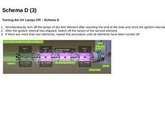
Turning the UV Lamps Off – Schema D -
Simultaneously turn off the lamps of the first element after reaching the end of the liner and once the ignition interval has elapsed.
-
After the ignition interval has elapsed, switch off the lamps of the second element.
-
If there are more than two elements, repeat this procedure until all elements have been turned off.
(Image: Turning the UV lamps off – Schema D) |
|
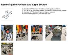
1. Allow the CIPP liner and the light source to gently cool down.
2. Turn off the air supply and release the pressure in a controlled manner.
3. Open the CIPP liner ends by removing the packers.
4. Remove the light source from the CIPP liner. (Image: The removal of the packers takes place with appropriate protective equipment) (Image: Removal of the packers) (Image: Removal of the packers 1) (Image: Removal of the packers – detail … |
|
-
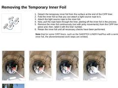
Detach the temporary inner foil from the surface at the end of the CIPP liner.
-
Fold the inner foil so that you can attach a light source rope to it.
-
Attach the light source rope to the inner foil.
-
Now, pull the rope back through the liner, peeling off the inner foil in the process.
-
Remove the inner foil continuously (not with jerky movements) from the CIPP liner in one piece and, then, label it with the liner number.
-
Retain …
|
|
-
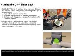
Cut the CIPP liner in the start and target manholes. Consider the following options in the process, depending on the type of end connection.
-
Flush with the manhole wall/pipeline
-
3 cm wide protrusion from the manhole wall/pipeline
-
Cut back inside the pipeline to prepare for installation of a CIPP liner end seal.
-
Remove the CIPP liner upper half shell in intermediate manholes (Image). Take into account any protrusions required at the cut edges …
|

|
|
|
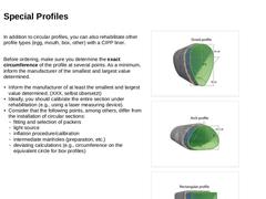
In addition to circular profiles, you can also rehabilitate other profile types (egg, mouth, box, other) with a CIPP liner.
Before ordering, make sure you determine the exact circumference of the profile at several points. As a minimum, inform the manufacturer of the smallest and largest value determined.
-
Inform the manufacturer of at least the smallest and largest value determined.
-
Ideally, you should calibrate the entire section under rehabilitation (…
|
|
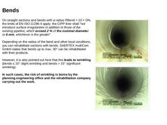
On straight sections and bends with a radius RBend > 10 × DN, the limits of EN ISO 11296-4 apply: the CIPP liner shall "not introduce surface irregularities in addition to those of the existing pipeline, which exceed 2 % of the nominal diameter or 6 mm, whichever is the greater".
Depending on the radius of the bend and other local conditions, you can rehabilitate sections with bends. SAERTEX multiCom GmbH states that bends up to max. 30° can be rehabilitated …
|
|
-
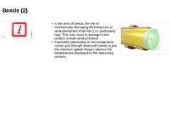
In the area of bends, the risk of mechanically damaging the temporary or semi-permanent inner foil (1) is particularly high. This may result in damage to the product or even product failure.
-
If possible (depending on the temperature curve), pull through areas with bends at just the minimum speed. Always observe the temperatures displayed by the measuring sensors.
(Image: Typical wall construction of lining tube ) |
|
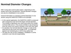
With "Lining with cured-in-place pipes", depending on the system limit of the manufacturer, nominal diameter changes can also be rehabilitated in one section. General information on changing nominal diameters in one section using the SAERTEX-LINER as an example: -
In this special application, the SAERTEX-LINER is produced with a temporary inner foil of the larger nominal diameter. This exhibits a significant over-sized area where the smaller nominal …
|
|
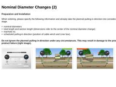
Preparation and Installation When ordering, please specify the following information and already take the planned pulling-in direction into consideration at this stage.
-
nominal diameters
-
total length and section length (dimensions refer to the center of the nominal diameter change)
-
manhole no.
-
scheduled pulling-in direction (position of cable winch and Liner box).
Do not ignore the planned pulling-in direction under any circumstances. This may … |
|
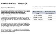
Preparation and Installation Take into account that the composite wall thickness/composite thickness cannot be changed inside such a CIPP liner. Having different composite wall thicknesses/composite thicknesses inside a section under rehabilitation is therefore not possible. A rehabilitation of nominal diameter changes within a section is possible using the example of the SAERTEX-LINER with the liner type S+: DN 150 - DN 1600 (only available with temporary … |
|
Preparation and Installation Select the light source taking the following criteria into consideration: -
The light source is suitable for both nominal pipe diameters and potential wrinkling of the inner foil is kept in mind when selecting the light source.
-
The corresponding curing parameters are available for both nominal diameters.
-
Select the working pressure for the smaller nominal diameter.
In the area of dimension changes, the risk … |
|

|
|
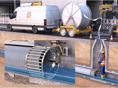
The given case of application presents the renovation of a defective sewer section consisting of concrete pipes DN 400 with a section length of 60 m by means of lining with spirally-wound pipes. This process belongs to the group of renovation processes and more specifically to lining with site-manufactured pipes.
|
|
Introduction: The renovation of sewers and pipelines with "Lining with cured-in-place pipes " is an established standard construction method, starting with the planning process, through material production and installation, right up to checking the quality achieved. It is characterised by a wide range of applications and a high variance in the fabrication and application processes. This unit teaches the essential basics in relation to the fabrication … |

|
|

|
|
|
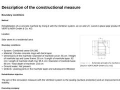
Boundary conditions Method Rehabilitation of a concrete manhole by lining it with the Vertiliner system, an on-site UV- cured-in-place pipe product from VERTILINER GmbH & Co. KG. (Image: Schematic principle of a manhole cross-section) Location Side street in a residential area Boundary conditions -
System: Combined sewer DN 300
-
Material: Circular concrete rings with brick taper
-
Dimensions of the manhole: Diameter of manhole cover: 55 cm / Height of manhole …
|
|
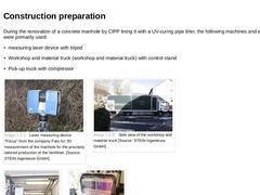
During the renovation of a concrete manhole by CIPP lining it with a UV-curing pipe liner, the following machines and equipment were primarily used: -
measuring laser device with tripod
-
Workshop and material truck (workshop and material truck) with control stand
-
Pick-up truck with compressor
(Image: Laser measuring device "Focus" from the company Faro for 3D measurement of the manhole ) (Image: Side view of the workshop and material truck ) (Image: … |