
|
|
|
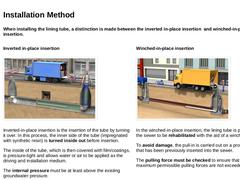
When installing the lining tube, a distinction is made between the inverted in-place insertion and winched-in-place insertion. Inverted in-place insertion (Image: Schematic diagram – Inverted in-place insertion) Inverted-in-place insertion is the insertion of the tube by turning it over. In this process, the inner side of the tube (impregnated with synthetic resin) is turned inside out before insertion. The inner surface of the tube, now covered with |
|
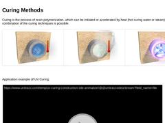
Curing is the process of resin polymerization, which can be initiated or accelerated by heat (hot curing water or steam) or UV light. A combination of the curing techniques is possible. (Image: Lining with cured-in-place pipes – principle of heat-initiated curing (hot curing with water) ) (Image: Lining with cured-in-place pipes – principle of heat-initiated curing (hot curing steam)) (Image: Lining with cured-in-place pipes – principle of light-initiated … |
|
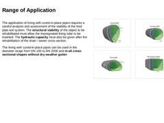
The application of lining with cured-in-place pipes (CIPP) requires a thorough analysis and assessment of the stability of the host pipe-soil system. The structural stability of the object to be rehabilitated must allow for the insertion of the impregnated lining tube. Additionally, the hydraulic capacity must be maintained after the rehabilitation of the drain/sewer cross-section. CIPP lining can be applied in a diameter range from DN 100 to DN 2000 |
|
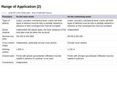
(Table: Lining with cured-in-place pipes - areas of application [Steinb]) |
|
|
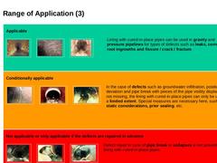
Applicable |
(Image: Corrosion of a concrete pipe) |
(Image: Example of root ingrowth) |
(Image: Example of fractures) |
Lining with cured-in-place pipes can be used in gravity and pressure pipelines for types of defects such as leaks, corrosion, root ingrowths and fissure / crack / fracture. |
|
Conditionally applicable |
(Image: Example of ground water infiltration) |
(Image: Example of positional deviation in vertical direction) |
(Image: Example of a pipe … |
|
|
|
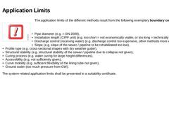
Important: The application limits of the different methods are determined by the following boundary conditions: -
Pipe diameter (e.g. > DN 2000),
-
Installation length (CIPP unit) (e.g. too short = not economically viable, or too long = technically not possible)
-
Discharge control (receiving water) (e.g. discharge control too expensive, other methods more economical)
-
Slope (e.g. slope of the sewer / pipeline to be rehabilitated too low),
-
Profile type (…
|

|
Feb 22, 2022
News
Hunter Water
Hunter Water is debuting an innovative new ‘keyhole’ technology for restoring damaged or degraded pipes in the Lower Hunter community.
|
|
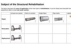
This figure illustrates the areas of application for the main types of rehabilitation. It clearly shows that both renovation and replacement impact at least one section of the sewer. |
|
At least one section |
Parts of a section |
Single Pipes |
Pipe Joints |
Lateral connections |
|
Repair |
|
(Image: Parts of section) |
(Image: Single pipes) |
(Image: Pipe joints) |
(Image: Lateral connections ) |
|
Renovation |
(Image: At least one section) |
|
|
|
|
|
Replacement |
|
|
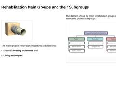
(Image: Lining with cured-in-place pipes) The main group of renovation procedures is divided into: -
(internal) Coating techniques
-
Lining techniques.
The diagram illustrates the main rehabilitation groups and their associated process subgroups. (Image: Overview of the main processing groups for the strucural rehabilitation and maintenance of drains and sewers) |

|
(Video: Lecture Video Lining with Cured-In-Place Pipes - processes) |
|
|
|
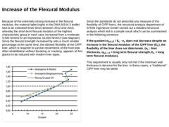
Because of the extremely strong increase in the flexural modulus, the material table (right) in the DWA-M144-3 leaflet had to be extended three times between 2012 and 2016, whereby the short-term flexural modulus of the highest characteristic group in each case increased from a moderate 9,500 N/mm2 to an impressive 16,000 N/mm2 (see diagram). Since the flexural strength increased by only a much smaller percentage at the same time, the desired flexibility |
|
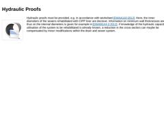
(Image: Picto Nutzungsdauer Duration of Use Hydraulic Proof) Hydraulic proofs must be provided, e.g. in accordance with worksheet [DWAA110:2012]. Here, the inner diameters of the sewers rehabilitated with CIPP liner are decisive. Information on minimum wall thicknesses and thus on the internal diameters is given for example in [DWAM144-3:2012]. If knowledge of the hydraulic capacity utilisation of the system to be rehabilitated is already known, a reduction … |
|
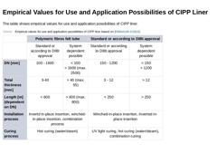
The table shows empirical values for use and application possibilities of CIPP liner. (Table: Empirical values for use and application possibilities of CIPP liner) |
|
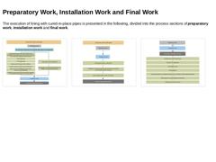
The execution of lining with cured-in-place pipes is presented in the following, divided into the process sections of preparatory work, installation work and final work. (Image: Schematic procedure for the execution of lining with cured-in-place pipes - Preparatory Work) (Image: Schematic procedure for the execution of lining with cured-in-place pipes - Installation work) (Image: Schematic procedure for the execution of lining with cured-in-place … |
|
|
|
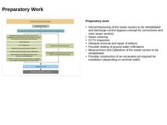
(Image: Schematic procedure for the execution of lining with cured-in-place pipes - Preparatory Work) Preparatory work -
Decommissioning of the sewer section to be rehabilitated and discharge control (bypass concept for connections and main sewer section)
-
Sewer cleaning
-
CCTV inspection
-
Obstacle removal and repair of defects
-
Possible sealing of ground water infiltrations
-
Measurement and calibration of the sewer section to be rehabilitated
-
Possibly
|
|
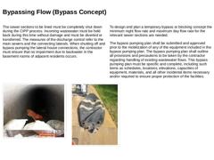
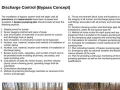
The sewer sections to be lined must be completely shut down during the CIPP process. Incoming wastewater must be held back during this time without damage and must be diverted or transferred. The measures of the discharge control refer to the main sewers and the connecting laterals. When shutting off and bypass pumping the lateral house connections, the contractor must ensure that no impairment due to backwater in the basement rooms of adjacent residents … |
|
The installation of bypass system shall not begin until all provisions and requirements have been reviewed and accepted. A bypass pumping plan should include at least the following aspects: -
Staging areas for pumps
-
Sewer plugging method and types of plugs
-
Size and location of manholes or access points for suction and discharge hose or piping
-
Size of pipeline or conveyance system to be bypassed
-
Number, size, material, location and method of installation …
|
|
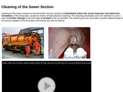
Cleaning of the sewer sections to be renovated must be carried out immediately before the visual inspection and before the installation of the lining tube, usually by means of high-pressure cleaning. The cleaning procedures are to be selected in such a way that further damage to the host pipe is avoided as far as possible. The cleaning process must allow a perfect determination of the actual condition of the host pipe and remove any and all internal. |
|
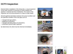
Directly before installation of the lining tube, a visual inspection of the sewer sections is necessary to check whether the pipeline is cleaned and free of obstacles. The results of the inspection are to be documented as a video on data media. Should significant deviations between the actual condition and the specified condition of the host pipe such as -
changed damage pattern,
-
additional connections,
-
changed operating status of connections,
-
unforeseen …
|
|
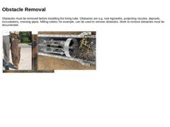
Obstacles must be removed before installing the lining tube. Obstacles are e.g. root ingrowths, projecting nozzles, deposits, incrustations, crossing pipes. Milling robots, for example, can be used to remove obstacles. Work to remove obstacles must be documented. (Image: Root ingress (BBA) - complex root system (C) in the pipe connection (A)) (Image: Root removed from a sewer) (Image: Root removal by use of a milling machine) |
|
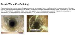
Repair work such as injection and/or filling procedures may be necessary before installation of the lining tube, in case of damage such as leaks, positional deviations (socket offsets), missing wall parts and damaged connection areas. For repairs, the data sheets ATV-DVWK-M 143-7, -8 and DWA-M 143-16 are to be applied. During this preparatory work, it is important to ensure that the installation of the lining tube is not adversely affected, e.g. by … |
|
Feb 22, 2022
News
Joshua Emerson Smith
Critics question costly investments in desalination given declining consumer demand. Supporters say long-term investments will bolster the region against future drought.
|