Chemically restoring pipeline position
Mar 17, 2011
Renovation
Current renewal methods for pipelines and culverts are very effective for pipe function decline and accident prevention, but offer little in the way of rehabilitating meandering and slacks of pipes. Continually expanding urbanisation means that restoring pipeline position using open cut methods has become less desirable, and as such has led to the development of new pipeline position restoration technologies, such as the chemical injection method.
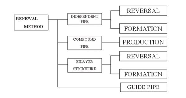
Figure 1. Classification of the renewal methods. (Source: Trenchless International)
| 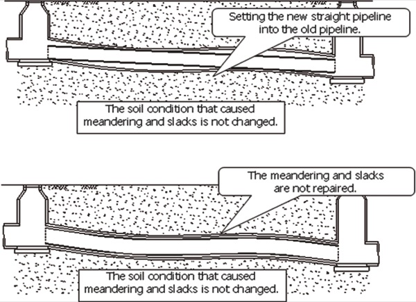
Figure 2. Illustration of pipeline after renewal construction. (Source: Trenchless International)
|
A technique commonly used for the improvement of subsided constructions is ground upheaval with injection grouting. However, it is difficult to define the amount of the injection grouting material that is necessary for position restoration of the pipeline, the shape of the pipe, and the impact to adjacent structures.
To overcome these problems, a new method has been developed that involves making a guide space formed primarily in the direction that the pipeline needs to be moved before construction. This process involves building casing pipes and a feeding pipe for injection grout. The feeding pipe is set at the guide space location. After pressurised slurry is sprayed from the feeding pipe to disturb the ground, the pipeline position may be improved.
This technique requires the consideration of drilling diameter, soil conditions, and the arrangement of the form and placement intervals of the feeding pipes. A suitable injection material requires a gelling time of around ten seconds with no change in strength, volume or weight after the injection. In cases of position restoration by grouting, a grouting material that uses two liquids, such as cement and sodium silicate, may be used. After each component is injected by a grouting pump into a guide space, both components are mixed in the same volume. However there are few materials that satisfy these requirements of cutting, mixing, and gelling. Moreover when using a pump, the injection performance and gelling time of the grouting material are not satisfied at the same time.
Thus, a new grouting material that suits the restoration method of the pipeline position via grouting was developed along with a method that enables the selection of the discharge quantity of different types of grouting material.
These days the extent of restoration and injection quantity of grouting materials is determined in advance, and optimal length and depth of injection are determined prior to construction. Figures 3 – 6 show the application procedures for the restoration method. After adopting the restoration method, snake-advancing and slack were rehabilitated with the underpinning effect and increased ground strength. Figure 7 shows the image of the soil condition after restoration.
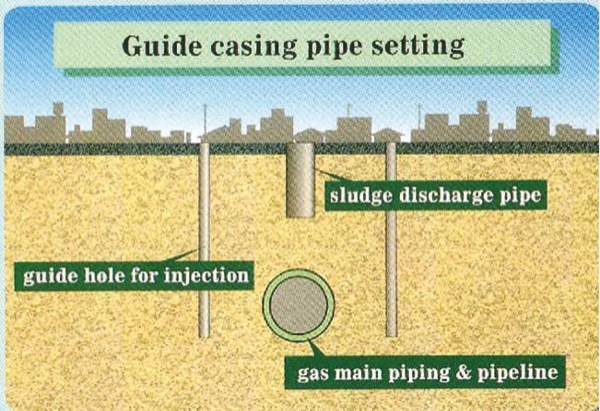
Figure 3. Guide casing pipe setting. (Source: Trenchless International)
| 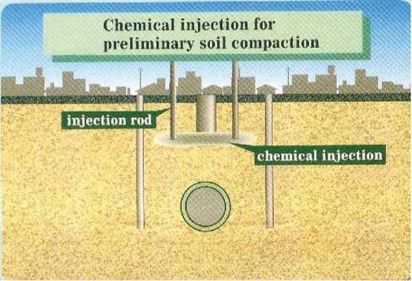
Figure 4. Chemical injection for preliminary soil compaction. (Source: Trenchless International)
|
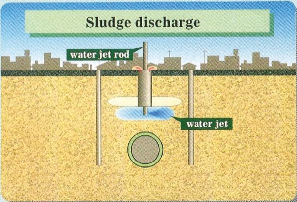
Figure 5. Sludge discharge. (Source: Trenchless International)
| 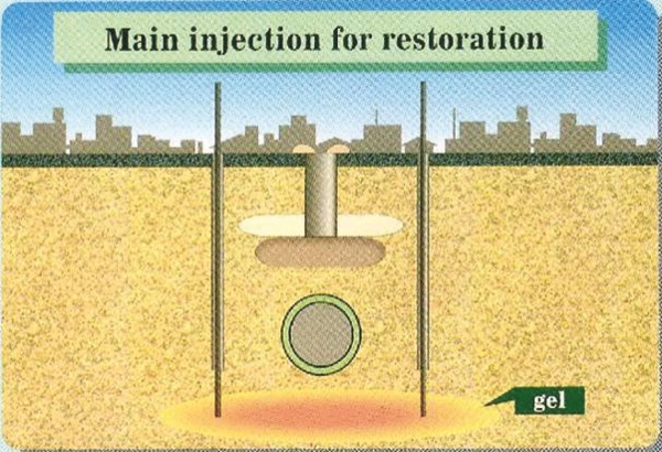
Figure 6. Main injection for restoration. (Source: Trenchless International)
|
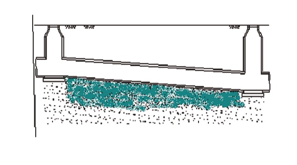
Figure 7. Image of the soil condition after construction. (Source: Trenchless International)
|
When restoring the position of a pipeline, an accurate survey of the location of the pipeline is typically required before developing a detailed layout of the restoration plan.
The measurement of the existing position is performed by optical survey and, where man-entry is possible, by manual logging with results contributing to background information for the restoration plan. However, in the case of gas or small conduit pipes when man-entry is not possible, two kinds of devices are used. The first is a camera with a survey instrument attached which is inserted into the pipe to measure its depth, as shown in Figure 8. The second is a device which directly measures the top positions of the pipeline as shown in Figure 9. This top position measurement system has been developed by the Department of Earth Resources Engineering at Kyushu University.
The top position measurement system involves preparing the casing pipe by drilling down to the pipe with pressurised slurry. The sprayed slurry is pumped from a tank on the surface and excavates and liquefies the soil, which is then continuously sucked from the casing pipe. After the hole has been extended to the top of the pipe a measuring rod is inserted into the drilled hole and the magnetised tip is set on top of the pipeline. This ability to establish existing conditions prior to construction works has resulted in improved site execution and management.
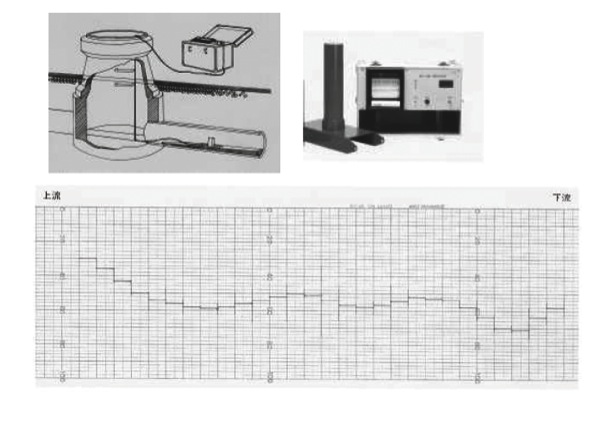
Figure 8. Image of the water level measurement, gauge, and recording paper. (Source Trenchless International)
| 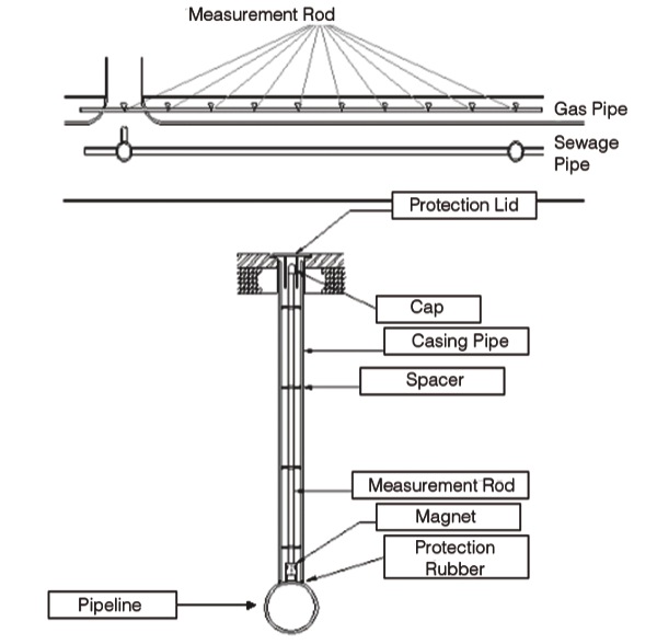
Figure 9. Measurement system for position of pipeline. (Source: Trenchless International)
|
Amount calculation of restoration method construction
When planning restoration and construction works, it is necessary to calculate the amount of injection.
Step one: determining the injection depth
It is necessary to consider upheaval pressure to ensure appropriate planning when determining the injection depth for the restoration constructions. A pulse injection is adopted because ground upheaval can be easily monitored and controlled, making it easier to repair the damaged pipes.
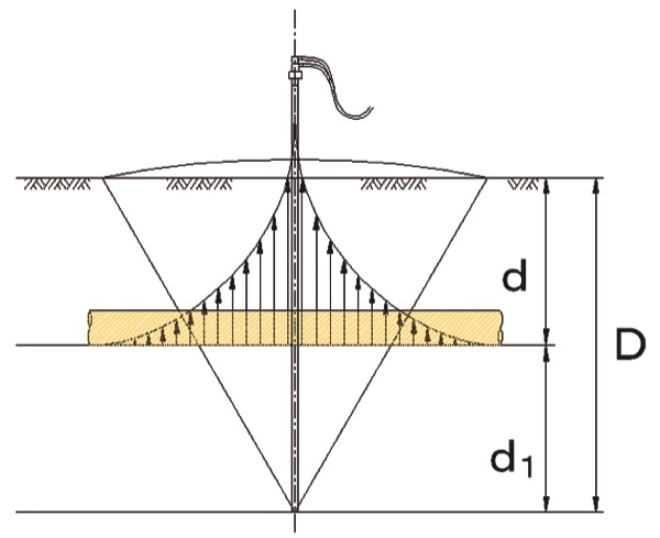
It is assumed that the effect of the pulse injection is defined as a cone, the centre of which is defined as the outflow point of the injection hole. The height and width of the cone are the distance from the centre to the real arrival points of the grouting material, as shown in Figure 10. It is supposed that the injection pressure of the grouting is acting within the range of the cone as mentioned above. For example, if the upheaval is measured 0.15 MPa at an injection depth of 10 metres and the radius of the cone is 10 metres, the vertical angle is 60 degrees. If the upheaval pressure is defined as the pressure required project from the pipeline, the injection depth is determined as follows.
D= d1+ d2 (1)
Where D, d1, and d2 are the injection depth, sum of overburden of the pipeline and diameter of the pipeline, and distribution depth of the pulse of the chemical grouting, respectively, d2 is calculated as follows;
(a) If the effective range of the pressure is acted in 1/3 of the injection effective radius,
V is the amount of injected grouting material and d2 is the distribution depth of the pulse of injection of the grouting material.
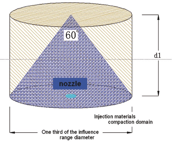
Figure 11. Injection range of grouting material. (Source: Trenchless International)
| 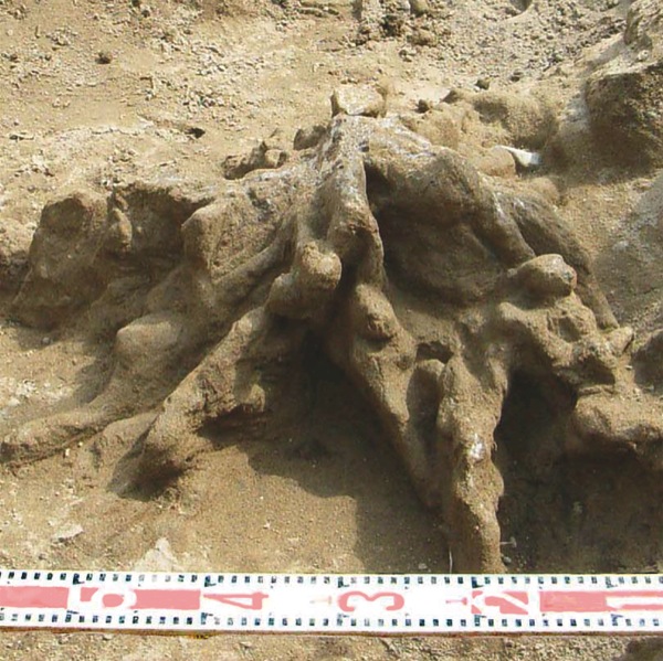
Figure 12. Distribution of the grouting materials. (Source: Trenchless International)
|
Step four: amount of injection for each pipe
Table 1: Comparison between prediction and the result of site investigation
| Item | Prediction | Result |
| Setting depth of injection pipe | Gl-6.1 Metres | Gl-6.1 Metres |
| Number of pipe | 14 | 14 |
| Injection amount | 8,147 Litres | 8,304 Litres |
More News and Articles
Aug 07, 2025
News
Kanalgipfel 2025: Netzweite operative Bedarfsplanung mittels individuellem Sanierungskosten- und Entscheidungsmodell
Die Entwässerungssysteme unserer Städte sind ein wesentlicher Bestandteil des kommunalen Anlagevermögens. Die große Zukunftsaufgabe, …
May 26, 2025
News
Kanalgipfel 2025: Smart Processing – mit KI-Technologien von der Kanalinspektion bis zur Sanierungsstrategie
Die Entwässerungssysteme unserer Städte sind ein wesentlicher Bestandteil des kommunalen Anlagevermögens. Die große Zukunftsaufgabe, …
May 12, 2025
News
Kanalgipfel 2025: Stand der Kanalsanierung in Deutschland – Eine kritische Betrachtung
Die Entwässerungssysteme unserer Städte sind ein wesentlicher Bestandteil des kommunalen Anlagevermögens. Die große Zukunftsaufgabe, vor der viele Kommunen …
Aug 28, 2024
News
ITpipes Secures $20M to Transform Water Infrastructure Management
ITpipes announced it has secured $20 million in equity financing from Trilogy Search Partners and Miramar Equity Partners.
Known for its trusted and user-friendly platform, ITpipes …
Aug 26, 2024
News
Professor Dr.-Ing. Dietrich Stein
With deep sadness we announce the loss of our founder and partner Prof Dr Dietrich Stein at the age of 85.
Engineers around the globe are thankful for his dedication to the inventions in the fields of sewers, …
Aug 26, 2024
News
PPI Releases New Installation Guide for PE4710 Pipe
PPI’s MAB-11-2024 Covers HDPE Water Pipelines Up to 60-in. Diameter and 10,000-ft Long Pulls
Developed by the Municipal Advisory Board (MAB) – and published with the help of the members of the …
Aug 23, 2024
News
Faster wide-scale leak detection now within reach
Mass deployment of connected leak loggers is being made possible by the latest technology, writes Tony Gwynne, global leakage solutions director, Ovarro
Water companies in England and Wales are …
Aug 21, 2024
News
Kraken awakens customer service potential in water
The innovative customer service platform Kraken has made a successful transfer from energy to water. Ahead of their presentation at UKWIR’s annual conference, Portsmouth Water chief executive …
Aug 19, 2024
News
Predicting the toxicity of chemicals with AI
Researchers at Eawag and the Swiss Data Science Center have trained AI algorithms with a comprehensive ecotoxicological dataset. Now their machine learning models can predict how toxic chemicals are …
Aug 16, 2024
News
Goodbye water loss: Trenchless pipe renewal in Brazil
Pipe renewal in Brazil
How do you stop water loss through leaks in old pipe systems without major environmental impacts and restrictions? The answer: with trenchless technology, or more precisely …
Aug 14, 2024
Article
Impact of high-temperature heat storage on groundwater
In a recently launched project, the aquatic research institute Eawag is investigating how the use of borehole thermal energy storage (BTES) affects the surrounding soil, the groundwater …
Aug 12, 2024
News
Watercare completes East Coast Bays sewer link
Watercare has successfully finished the final connection on the East Coast Bays link sewer at Windsor Park in New Zealand.
Much of the East Coast Bays sewer link was installed using horizontal directional …
Contact
Great Southern Press
Masahi Komura, Koichi Araki, Hideki Shimada, Takashi Sasaoka, Kikuo Matsui and Takahisa Tomii
