|
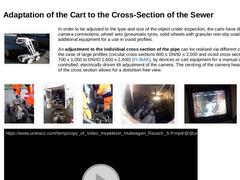
(Image: Trolley with electric lifting gear and camera) In order to be adjusted to the type and size of the object under inspection, the carts have different camera connections, wheel sets (pneumatic tyres, solid wheels with granular non-slip coatings, etc.) and additional equipment for a use in ovoid profiles. An adjustment to the individual cross section of the pipe can be realised via different cart sizes, or, in the case of large profiles (circular … |
|
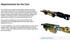
The chassis (e.g. wheels or track-driven chassis has to be constructed to allow the cart to develop the required traction force, keep the cart on track and prevent overturning. For that purpose, some manufacturers offer an electronic stabilisation function, providing an active overturning prevention and keeping the cart safe on its way along the pipe invert. The remote-controlled cart has to travel forwards and backwards at a controllable speed and … |

|
The power supply of the camera and the data transfer are both realised via a special cable (subsequently also called camera cable) that is either stored on a motor-driven cable winch or a manually operated cable drum. Generally, the camera cable is a multifunctional cable that is used for the power supply of the camera, cart and lighting as well as for data transfer (transfer of image information and control commands). When a cart is used, the length … |

|
Satellite sewer TV camera systems are used for the combined inspection of non-accessible sections and their connection sewers. They are composed of a cart camera and an additional electrically controllable axial view or pan and tilt camera, which is also called satellite sewer TV camera or lateral camera. The former is used to inspect the main sewer and to position the satellite sewer TV camera in the inlet area of the respective building connection … |
|
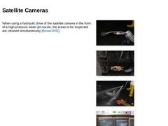
When using a hydraulic drive of the satellite camera in the form of a high-pressure water jet nozzle, the areas to be inspected are cleaned simultaneously [Bosse2005]. (Image: Positioning the satellite camera in front of the connecting opening) (Image: Positioning of the satellite camera system in the sewer) (Image: Flushing Camera - TV Inspection Camera with Hydraulic Drive) (Image: Satellite camera system with hydraulic drive in operation) |

|
The inspection of branched private domain sewer systems or entire drain systems starting from an access point in the main sewer is impossible with the above-mentioned satellite sewer TV camera system. This case of application requires special inspection systems. These include: -
Satellite camera systems with telescopic directional guidance
-
Satellite camera systems with stationary directional guidance
-
Flushing cameras with integrated module for leak …
|
|
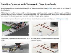
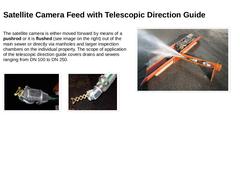
A representative of this inspection technology is the telescopic direction guide [FI-Jtele] that is based on the satellite camera systems described prior. Additionally, the satellite camera, which is in this case a pan and tilt camera, is equipped with a telescopic pan/tilt direction guide. It is extended and retracted by means of a windable/unwindable rope in the camera head. A pull-spring is installed for stabilisation at both ends of the direction … |
|
The satellite camera is either moved forward by means of a pushrod or it is flushed (see image on the right) out of the main sewer or directly via manholes and larger inspection chambers on the individual property. The scope of application of the telescopic direction guide covers drains and sewers ranging from DN 100 to DN 250. (Image: Telescopic forced guidance in retracted state) (Image: Telescopic forced guidance in extended state) |
|
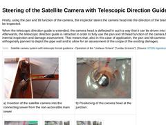
Firstly, using the pan and tilt function of the camera, the inspector steers the camera head into the direction of the branched pipe to be inspected. When the telescopic direction guide is extended, the camera head is deflected in such a way that it can be driven into the branch. Afterwards, the telescopic direction guide is retracted in order to fully use the pan and tilt head function of the camera for a visual internal inspection and damage assessment. … |
|
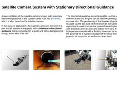
A representative of the satellite camera system with stationary directional guidance is the system called “Kiel rod” [FI-IBAK], which is also based on the satellite camera. In this case of application, the satellite camera in the form of a pan and tilt camera is equipped with a stationary directional guidance that is composed of a guide unit with a ball placed at its top, also called “Kiel rod”. The directional guidance is exchangeable, so that units … |

|
|
|
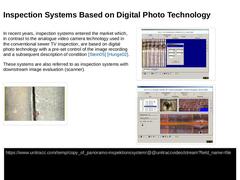
In recent years, inspection systems entered the market which, in contrast to the analogue video camera technology used in the conventional sewer TV inspection, are based on digital photo technology with a pre-set control of the image recording and a subsequent description of condition [Stein05] [Hunge02]. These systems are also referred to as inspection systems with downstream image evaluation (scanner). (Image: Recording of the condition image "pipe … |
|
This method uses high-definition fully spherically, hemispherically or cylindrically recording wide angle cameras with fisheye objective lenses (scanner). The digitally recorded, discrete individual images of the photographed interior pipe wall over the entire sewer section length are put together by means of special digital image processing programmes. Afterwards they are digitally processed into a seamless media file that can be monitored later … |
|
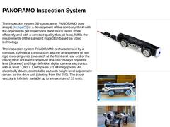
The inspection system 3D optoscanner PANORAMO (see image) [Hunge02] is a development of the company IBAK with the objective to get inspections done much faster, more efficiently and with a constant quality that, at least, fulfills the requirements of the standard inspection based on video technology. The inspection system PANORAMO is characterised by a compact, cylindrical construction and the arrangement of two rigid recording units (one each at … |

|
In contrast to the analogue video camera technology that is used in the conventional sewer TV inspection, this system, for the first time, implements and combines the fully digital, fully spherical image recording and processing (panorama technology) as well as the assessment of the condition of drains and sewers from DN 150 (IBAK PANORAMO 150) or DN 200 (IBAK PANORAMO) that no longer needs to be done in situ by the inspector, but rather afterwards, … |

|
The performance capacity and quality of the recorded images are not only determined by the hardware, but also by the required image processing and –interpretation software. In order to record the individual images, the PANORAMO scanner software uses two modes: -
Scan mode (Standard operation)
-
Video mode (optional choice)
|
|
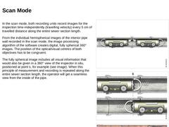
In the scan mode, both recording units record images for the inspection time-independently (travelling velocity) every 5 cm of travelled distance along the entire sewer section length. From the individual hemispherical images of the interior pipe wall recorded in the scan mode, the image processing algorithm of the software creates digital, fully spherical 360° images. The position of the optical/visual centres of both objectives has to be congruent. |
|
In the next step, the fully spherical images are processed into a seamless data string. This string allows for an examination of the pipe with a continuous sequence of images during the evaluation of the inspection later on. Using real-virtual intermediate images that are based on computer calculations (IBAK patent), the panorama images that are recorded with an image frequency of 7 images/s (maximum travelling velocity 35 cm/s and object-image distance … |
|
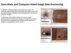
In addition to the perspective (full spherical) record, the computer-aided image data processing also allows a clear, flat (two-dimensional) unfolding of the photographed interior pipe wall (see images). Furthermore, the software allows for a true-to-scale representation of ovoid cross sections in processing and the measurement of obstacles that intrude into the pipe cross section in a perspective view [FI-IBAK]. (Image: Example of perspective view (… |
|
In the video mode, which can be set optionally by the operator at the touch of a button in the observation/direction room of the inspection vehicle, both cameras can be operated time-controlled and in real time just like common video cameras. It can be chosen which records (those of the camera at the front or at the back) are transmitted onto the monitor in the form of digital video data. If a video capture card is at hand, the data can be recorded … |
|
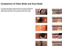
To compare the video mode and the scan mode, the following images are tabulated. Column 1 shows screenshots of the video mode and column 2 screenshots of the scan mode. (Image: Screenshot video mode - concrete sewer - damaged connection / connection incompletely integrated) (Image: Screenshot of video mode - vitrified clay sewer - protruding connection / connection incompletely integrated and longitudinal crack) (Image: Screenshot of the scan mode - … |
|
As only individual images are recorded at a distance of 5 cm, the PANORAMO system uses a Xenon flash light at the front and rear end of the drive and transportation unit. It is installed behind a translucent pane each and has the essential advantage of a very short illumination of 1/2,000 s per image. It also aids a recording of sharp images without motion blur despite a high travelling velocity. (Video: Video IBAK Panoramo - Xenon flash illumination) |
|
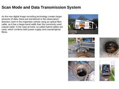
As the new digital image recording technology creates larger amounts of data, these are transferred to the observation/direction room in the inspection vehicle using an optical fibre cable, as it has a larger band width than the commonly used coaxial cable. In the case at hand, so-called hybrid cables are used, which combine both power supply and coaxial/optical fibres. (Image: PANORAMO inspection system in practical use - view of the inspection vehicle) (… |
|
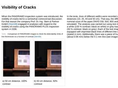
When the PANORAMO inspection system was introduced, the visibility of cracks led to a somewhat controversial discussion. For that reason the company Prof. Dr.-Ing. Stein & Partner GmbH [Stein06] engaged in analyses with regard to the visibility of cracks using the PANORAMO PLUS inspection system in 2006. (Table: Comparison of PANORAMO images to check the detectability limits of line thicknesses as a function of contrast.) In the tests, lines of different … |
|
Based on these results, analyses of the “Berliner Wasserbetriebe” [Hilpe2003] and experiences of the manufacturer, the company IBAK determines the lower visibility limit for crack widths with 1/10,000 or 0.01% of the internal pipe diameter. For a pipe of the nominal size DN/ID 500 (500 mm), this would mean that cracks would be visible down to a width of W = 500 mm/10,000 = 0.05 mm, for example. Thus, in this case, this inspection system meets all … |