
|
|

|
Geoelectrics are used to locate objects and structures that have a different electrical resistance than their environment. A distinction can be made between galvanic and capacitive geoelectrics. In the first case, the electrodes and measuring probes are put into the ground in the form of metal stakes and thus galvanically coupled. In the case of the capacitive coupled geoelectrics, the electrodes are made of a metallic cable that is isolated against … |
|
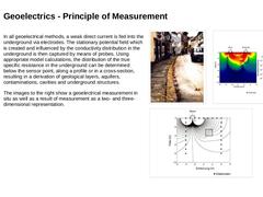
In all geoelectrical methods, a weak direct current is fed into the underground via electrodes. The stationary potential field which is created and influenced by the conductivity distribution in the underground is then captured by means of probes. Using appropriate model calculations, the distribution of the true specific resistance in the underground can be determined below the sensor point, along a profile or in a cross-section, resulting in a … |
|
Using the capacitive coupled geoelectrical measurement, velocities between 1.5 km/h and 2 km/h are possible for the detection of bedding defects in the road area. Depending on the type of the measurement equipment, data can be captured at the same time from up to six different depths up to a maximum depth of about 6 m. The resolution of the method depends on the resistance contrast between the “undisturbed” soil and the defects (bedding defect = … |

|
The method is not to be recommended or rather limited in its use given the following limiting conditions: -
Small investigation area (spatially limited, dimensions of only a few metres),
-
Existence of metallic lines running in parallel to the line to be explored (applies to the linear dipole-dipole method only),
-
Given a necessary maintenance of motor traffic.
Under favourable conditions (that is, with resistance differences of > 10 %) intra-urban … |

|
|
|
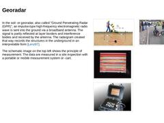
In the soil- or georadar, also called ”Ground Penetrating Radar (GPR)”, an impulse-type high-frequency electromagnetic radio wave is sent into the ground via a broadband antenna. The signal is partly reflected at layer borders and interference bodies and received by the antenna. The radargram created that way records the structures in the underground in an interpretable form [Lenz97]. The schematic image on the top left shows the principle of measurement. … |
|
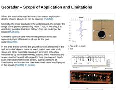
When this method is used in intra-urban areas, exploration depths of up to about 4 m can be reached [Pulsf96]. Normally, the more conductive the underground, the smaller the range of the ground-penetrating radar. Thus, in wet clay, it is absolutely possible that lines below 1.5 m can no longer be located [Katha91]. Unsealed cohesive and very inhomogeneous soils also represent physical limitations of use for the geo-radar [Busch96]. In the area that … |
|
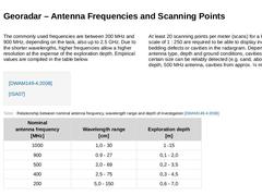
The commonly used frequencies are between 200 MHz and 900 MHz, depending on the task, also up to 2.5 GHz. Due to the shorter wavelengths, higher frequencies allow a higher resolution at the expense of the exploration depth. Empirical values are compiled in the table below. At least 20 scanning points per meter (scans) for a longitudinal scale of 1 : 250 are required to be able to display individual bedding defects or cavities … |
|
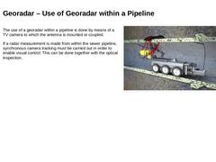
The use of a georadar within a pipeline is done by means of a TV camera to which the antenna is mounted or coupled. If a radar measurement is made from within the sewer pipeline, synchronous camera tracking must be carried out in order to enable visual control. This can be done together with the optical inspection. (Image: Georadar measurements from the pipeline - Camera vehicle - Neu) |
|
-
The large-scale use of georadar can reduce the number of direct and indirect exploration required. Since their use only serves to verify the georadar measurement.
-
In addition, critical areas can be better identified, so that narrow search grids are no longer necessary.
-
As both the road structure and the subsurface are investigated with georadar, rehabilitation decisions can be derived for the road / traffic department at the same time.
|

|
|
|
Advantages of geophysical methods The advantage of geophysical measuring methods is that a usable statement about the non-visible areas outside the sewer wall and below the road surface in the existing subsurface and in the backfilling of the pipe trench can be made with relatively little effort. The following criteria have to be taken into consideration [Reute92] [Altha99]: |
|
Disadvantage of geophysical methods A device-specific disadvantage of geophysical methods is that all signals have to penetrate layers that are often very inhomogeneous, earthwork and road surfaces before they reach the measuring object. Thus, the virtual signal can be strongly disturbed, resulting in useless measurement data. What does the selection of the most suitable method depend on? Consequently, the choice of the geophysical … |
|
What influences the significance and reliability of geophysical measurements? The methods used in the field campaign and the adequate arrangement of the measurement equipment are of great importance with respect to the significance and reliability of geophysical measurements. Geophysical results of measurement are ambiguous by their nature and there exists a high complexity of correlations between the stimulating signal and the response behaviour … |
|
Which boundary conditions influence the choice of geophysical exploration methods? The choice of suitable geophysical methods of exploration for the assessment of the pipe-soil-system’s condition is influenced by the following limiting conditions: -
Structural condition of the sewer,
-
Structures and systems above ground and underground as well as green areas,
-
Sewer length, -line, -depth and -geometry,
-
Subsoil and groundwater conditions (e.g. maximum …
|
|
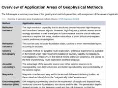
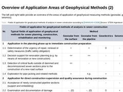
The following is a summary overview of the geophysical methods presented, with assignment of the areas of application. (Table: Overview of application areas of geophysical methods) |
|
The left and right table provide an overview of the areas of application of geophysical measuring methods (georadar, geoelectrics, seismics). (Table: Fields of application for geophysical methods of analysis in sewer construction according to DWA-M 149-4) (Table: Impact of the underground onto the possible fields of application for geophysical methods according to DWA-M 149-4) Important: None of the geophysical methods explained above is suitable to … |
|
|
|
(Image: Picto Bodenuntersuchung) The results of the geotechnical investigations and laboratory analyses have to be determined by a subsoil expert and then written down in a geotechnical report. The geotechnical report (in practice also called subsoil report or subsoil expertise) includes the geotechnical investigation report according to Eurocode 7 (EC 7). This report forms part of the geotechnical design report in accordance with EC 7, which additionally … |
|
This module teaches the basics of geophysical soil investigation and is to be understood as a supplement to the module "Geotechnical Investigation". Geophysical measurement methods belong to the indirect exploration methods and allow statements regarding local inhomogeneities in the pipeline zone (e.g. bedding defects, cavities, disruptions, concrete encasements) or, in the case of investigations of existing sewers and pipelines, statements regarding the condition and load-bearing capacity of the embedment. In addition to ground or georadar (EMR - electromagnetic reflection), which is well-known in pipeline construction and rehabilitation, the measurement methods seismic, seismic tomography, air gun seismic, magnetics, electromagnetics and geoelectrics are also introduced. After completing this module, you will have knowledge regarding: - Procedural principles and
- Assignment of application areas to procedures of geophysical ground investigation.
|
|
Summary This lesson builds on the module "Application of coding systems using the example of EN 13508-2" and introduces the coding of damage (findings) for sewers and drains. In more detail, the causes and consequences of damage are explained for the damage and, in some cases, the damage mechanisms are presented as well.
Learning Objectives Upon successful completion of this course, you will be able to: |
|
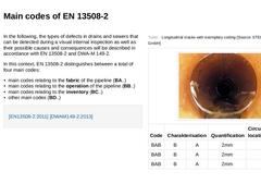
In the following, the types of defects in drains and sewers that can be detected during a visual internal inspection as well as their possible causes and consequences will be described in accordance with EN 13508-2 and DWA-M 149-2. In this context, EN 13508-2 distinguishes between a total of four main codes: -
main codes relating to the fabric of the pipeline (BA..)
-
main codes relating to the operation of the pipeline (BB..)
-
main codes relating to …
|
|
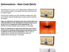
According to [EN13508-2:2011], deformation is defined as “the cross-sectional shape of the pipeline has been deformed from its original shape". For this type of defect, the client will define whether this code must only be used for flexible pipes or pipes made of all kinds of material. Pipes are defined to be flexible when their deformation has essential effects on the distribution of loads and pressure, as the soil is a component of the load-bearing |
|
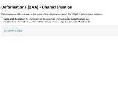
Deformation is differentiated on the basis of the deformation curve. EN 13508-2 differentiates between: -
vertical deformation δv - the height of the pipe has changed (code specification A)
-
horizontal deformation δh - the width of the pipe has changed (code specification B)
|