|
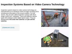
Inspection systems based on video camera technology are characterised by an individual control of image recording and a simultaneous description of the actual condition. For that reason, they are also called inspection systems with direct image control and –evaluation. There exist different camera types with analogue and/or digital signal output. They are distinguished into axial view cameras and pan and tilt cameras. |
|
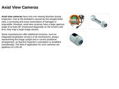
Axial view cameras have only one viewing direction during inspection. Due to the limitations caused by this straight-lined view, a surveying and exact examination of damages is impossible. However, axial view cameras have a large aperture angle of at least 90° (measured diagonally on the screen) and thus, they map a large image section. Some manufacturers offer additional functions, such as integrated localisation sensors or tilt mechanisms, always … |
|
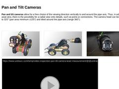
Pan and tilt cameras allow for a free choice of the viewing direction vertically to and around the pipe axis. Thus, in addition to the axial view, there is the possibility for a radial view onto details, such as joints or connections. The camera head can be panned by up to 320° (pan area minimum ±135°) and tilted around the pipe axis (range 360°). (Image: TV inspection system - Turn/swivel head camera of the company JT-elektronik GmbH with trolley - … |
|
Pan and tilt cameras are usually applied in the inspection of pipes from DN 100, partly also in smaller nominal sizes. Some manufacturers also offer the above-mentioned tilt mechanisms for an upright and correctly positioned image. Furthermore, the cameras are equipped with automatic functions, e.g. to swerve into pipe connections or for a programmable line of vision [FI-IBAK]. Depending on the individual type, cameras have a fixed focus, autofocus … |
|
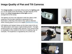
The image quality is essentially influenced by the lighting unit (i.e. by the quality of the illumination, the light intensity of the lamps, the colour temperature of the light and the arrangement of the lamps. The lighting unit has to be adjusted to both the object under inspection and the pipe materials to guarantee for an illumination uniformity of the field of view without reflection while covering about 3 m to 4 m in depth [DWAM149-5:2010]. LED … |
|
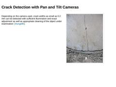
Depending on the camera used, crack widths as small as 0.2 mm can be detected with sufficient illumination and exact adjustment as well as appropriate cleaning of the object under examination [Hunge80]. (Image: Crack in a concrete pipe) |
|
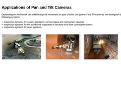
Depending on the field of use and the type of movement or type of drive unit (drive of the TV camera), we distinguish between the following systems: -
Inspection systems for sewers (sections, service pipes and connection sewers)
-
Inspection systems for the combined inspection of sections and their connection sewers
-
Inspection systems for drain systems.
(Image: TV inspection system for combined inspection of sewer pipes and their connecting sewers - … |
|
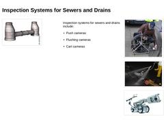
Inspection systems for sewers and drains include: -
Push cameras
-
Flushing cameras
-
Cart cameras
(Image: TV push camera of the company RITEC) (Image: Flushing Camera - TV Inspection Camera with Hydraulic Drive) (Image: Height adjustable trolley with side guide for oval pipes) |
|
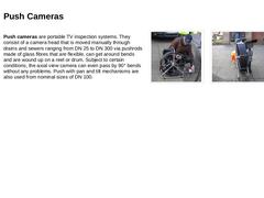
Push cameras are portable TV inspection systems. They consist of a camera head that is moved manually through drains and sewers ranging from DN 25 to DN 300 via pushrods made of glass fibres that are flexible, can get around bends and are wound up on a reel or drum. Subject to certain conditions, the axial view camera can even pass by 90° bends without any problems. Push with pan and tilt mechanisms are also used from nominal sizes of DN 100. |
|
The use of push cameras requires access points to the inspection object. These are, for example, manholes, inspection chambers, catch basins, but also “potential access” at downpipes, sanitary installations and floor drains in buildings. (Video: Inspection by means of a pushrod camera) |
|
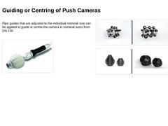
Pipe guides that are adjusted to the individual nominal size can be applied to guide or centre the camera in nominal sizes from DN 100 (Image: Push camera with accessories (pipe guide for DN 100)) (Image: Ritec roller slides from DN 150 (front and rear view)) (Image: RITEC push guides (left DN 160 and right DN 100)) |
|
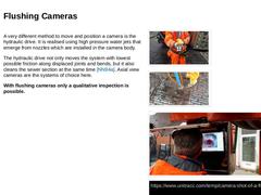
A very different method to move and position a camera is the hydraulic drive. It is realised using high pressure water jets that emerge from nozzles which are installed in the camera body. The hydraulic drive not only moves the system with lowest possible friction along displaced joints and bends, but it also cleans the sewer section at the same time [NN94a]. Axial view cameras are the systems of choice here. With flushing cameras only a qualitative … |
|
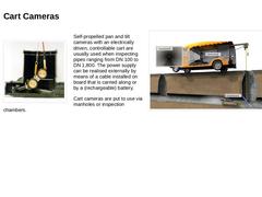
(Image: Insertion of the TV camera into a DN 150 pipe through an inspection opening with a diameter of 300 mm [FI-IBAK]) Self-propelled pan and tilt cameras with an electrically driven, controllable cart are usually used when inspecting pipes ranging from DN 100 to DN 1,800. The power supply can be realised externally by means of a cable installed on board that is carried along or by a (rechargeable) battery. Cart cameras are put to use via manholes … |
|
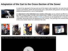
(Image: Trolley with electric lifting gear and camera) In order to be adjusted to the type and size of the object under inspection, the carts have different camera connections, wheel sets (pneumatic tyres, solid wheels with granular non-slip coatings, etc.) and additional equipment for a use in ovoid profiles. An adjustment to the individual cross section of the pipe can be realised via different cart sizes, or, in the case of large profiles (circular … |
|
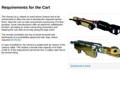
The chassis (e.g. wheels or track-driven chassis has to be constructed to allow the cart to develop the required traction force, keep the cart on track and prevent overturning. For that purpose, some manufacturers offer an electronic stabilisation function, providing an active overturning prevention and keeping the cart safe on its way along the pipe invert. The remote-controlled cart has to travel forwards and backwards at a controllable speed and … |

|
The power supply of the camera and the data transfer are both realised via a special cable (subsequently also called camera cable) that is either stored on a motor-driven cable winch or a manually operated cable drum. Generally, the camera cable is a multifunctional cable that is used for the power supply of the camera, cart and lighting as well as for data transfer (transfer of image information and control commands). When a cart is used, the length … |
|
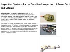
Satellite sewer TV camera systems are used for the combined inspection of non-accessible sections and their connection sewers. They are composed of a cart camera and an additional electrically controllable axial view or pan and tilt camera, which is also called satellite sewer TV camera or lateral camera. The former is used to inspect the main sewer and to position the satellite sewer TV camera in the inlet area of the respective building connection … |
|
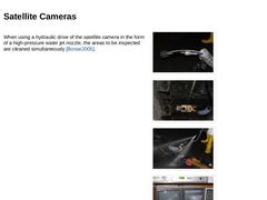
When using a hydraulic drive of the satellite camera in the form of a high-pressure water jet nozzle, the areas to be inspected are cleaned simultaneously [Bosse2005]. (Image: Positioning the satellite camera in front of the connecting opening) (Image: Positioning of the satellite camera system in the sewer) (Image: Flushing Camera - TV Inspection Camera with Hydraulic Drive) (Image: Satellite camera system with hydraulic drive in operation) |
|
The inspection of branched private domain sewer systems or entire drain systems starting from an access point in the main sewer is impossible with the above-mentioned satellite sewer TV camera system. This case of application requires special inspection systems. These include: -
Satellite camera systems with telescopic directional guidance
-
Satellite camera systems with stationary directional guidance
-
Flushing cameras with integrated module for leak …
|
|
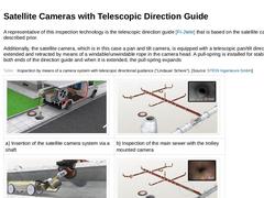
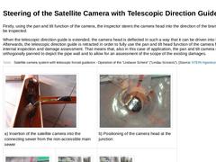
A representative of this inspection technology is the telescopic direction guide [FI-Jtele] that is based on the satellite camera systems described prior. Additionally, the satellite camera, which is in this case a pan and tilt camera, is equipped with a telescopic pan/tilt direction guide. It is extended and retracted by means of a windable/unwindable rope in the camera head. A pull-spring is installed for stabilisation at both ends of the direction … |
|
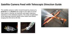
The satellite camera is either moved forward by means of a pushrod or it is flushed (see image on the right) out of the main sewer or directly via manholes and larger inspection chambers on the individual property. The scope of application of the telescopic direction guide covers drains and sewers ranging from DN 100 to DN 250. (Image: Telescopic forced guidance in retracted state) (Image: Telescopic forced guidance in extended state) |
|
Firstly, using the pan and tilt function of the camera, the inspector steers the camera head into the direction of the branched pipe to be inspected. When the telescopic direction guide is extended, the camera head is deflected in such a way that it can be driven into the branch. Afterwards, the telescopic direction guide is retracted in order to fully use the pan and tilt head function of the camera for a visual internal inspection and damage assessment. … |
|
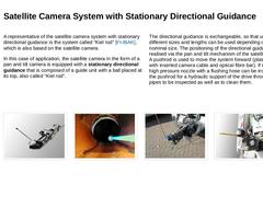
A representative of the satellite camera system with stationary directional guidance is the system called “Kiel rod” [FI-IBAK], which is also based on the satellite camera. In this case of application, the satellite camera in the form of a pan and tilt camera is equipped with a stationary directional guidance that is composed of a guide unit with a ball placed at its top, also called “Kiel rod”. The directional guidance is exchangeable, so that units … |
|
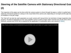
The inspection of the pipes can be done while the camera system is driven through the pipes or while it is pulled back out. The stationary directional guidance is always in the visual field of the camera and, depending on its length and the pipe diameter, it leads to limitations in the pan range. The “Kiel rod” can also be used separately as a push camera with manual drive via manholes or larger inspection chambers on the property. The field of application … |

|
|