|
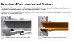
The connections of pipes to manholes and structures must be articulated. A concrete seat may also be installed under the connection to provide added support. The same applies if settlement is expected. In addition, when connecting lateral sewer pipes to manholes, flexible watertight connectors should be used, unless otherwise specified in the owner's specifications. (Image: Lateral joint connection – concrete pipe) (Image: Lateral joint connection – … |
|
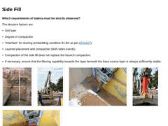
Which requirements of statics must be strictly observed? The decisive factors are: -
Soil type
-
Degree of compaction
-
"Interface" for shoring (embedding condition B1-B4 as per [ATVA127])
-
Layered placement and compaction (both sides evenly)
-
Compaction of the side fill does not replace the haunch compaction.
-
If necessary, ensure that the filtering capability towards the bedding layer beneath is always sufficiently stable.
(Image: Bedding compaction … |
|
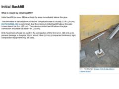
(Image: Hand tamper) What is meant by initial backfill? Initial backfill (or cover fill) describes the area immediately above the pipe. The thickness of the initial backfill in the compacted state is usually 12-in. (30 cm). [[ASTM D2321–05]] recommends that the minimum initial backfill above the pipe crown should be 6-in. (15 cm). The minimum initial backfill above the pipe connection should be at least 4-in. (10 cm). Only hand tools should be used in … |
|
What are decisive factors, which need to be considered during installation of the final (or main) backfill? The requirements of statics must be strictly observed. The decisive factors are: -
Soil type (not to be "better" than in situ soil)
-
Degree of compaction
-
"Interface" for shoring
-
Layered placement and compaction
-
No use of heavy compaction equipment up to 3 feet (1.0 m compacted thickness) above the pipe crown
-
Vibration energy of the compaction …
|

|
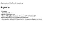
The backfill of the embedment differs between four conditions [ATVA127]: (Table: Cover Filling Conditions A1-A4 as per ATV-DVWK-A 127) |
|
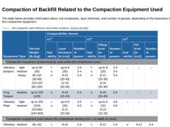
The table below provides information about soil compaction, layer thickness, and number of passes, depending on the heaviness of the compaction equipment. (Table: Soil compaction, layer thickness, and number of passes [DWAA139]) (Table: Soil Classification (DWA-A 139)) |
|
|
|
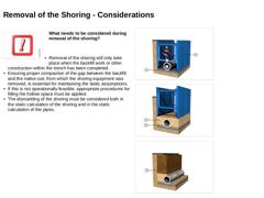
(Image: Attention!) What needs to be considered during removal of the shoring? -
Removal of the shoring will only take place when the backfill work or other construction within the trench has been completed.
-
Ensuring proper compaction of the gap between the backfill and the native soil, from which the shoring equipment was removed, is essential for maintaining the static assumptions.
-
If this is not operationally feasible, appropriate procedures for …
|
|
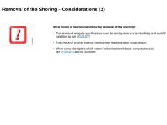
What needs to be considered during removal of the shoring? -
The structural analysis specifications must be strictly observed (embedding and backfill condition as per [ATVA127]
-
The choice of another shoring method may require a static recalculation.
-
When using sheet piles which extend below the trench base, computations as per [ATVA127] are not sufficient.
|
|
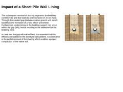
The subsequent removal of shoring segments (embedding condition B2 and B3) leads to a stress factor of 2.5 or more. Through the created gap (between native ground and trench backfill) is the formation of a “silo effect" prevented. Furthermore, undermining of the bedding support can occur within the gap (left), hence resulting in the settlement of the bedding zone. In case that the gap will not be filled, it is essential that this effect is considered … |
|
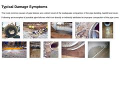
The most common causes of pipe failures are a direct result of the inadequate compaction of the pipe bedding, backfill and cover. Following are examples of possible pipe failures which are directly or indirectly attributed to improper compaction of the pipe zone. (Image: Longitudinal failure) (Image: Inappropriate use of a heavy compactor) (Image: Failure to meet the minimum trench width) (Image: Failure to meet the minimum trench width) (Image: Inadequately … |
|
|
|
|
|
Flowable fill is a self-compacting low strength material with a flowable consistency that is used as an economical fill or backfill material, as an alternative to compacted granular fill. Flowable fill is not concrete nor it is used to replace concrete. Terminology used by [[ACI 229R]] for this material are unshrinkable fill, controlled density fill, flowable mortar or lean-mix backfill. On the following pages are presented the advantages and disadvantages … |
|
Hydraulically bounded filling materials consist principally of the following raw materials: -
Filler material, such as native aggregates or recycled materials
-
Plasticizer, for example, mixture of water swellable clay (bentonite), foaming agents, air pore-forming additives (surfactants) or other mineral, organic and / or inorganic additives,
-
Stabilizer (binder), such as cement or lime.
The hydraulically bonded fill mixture is composed of about 95% … |
|
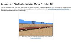
After the trench has been excavated and shored, the pipeline is alligned and fixed to the trench base in accordance with the planning specifications either on wooden boards or sandbags (based on the calculation concept by [Prof. Dr.-Ing. Stein & Partner GmbH], the latter are to be preferred for structural reasons). (Image: Pipe string aligned and bedded on the trench base and on sandbags) |
|
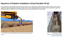
Prior to pouring of the hydraulic fill from the ready mix truck, a so-called anchor saddle of the same filler material, but in a firmer consistency, has to be poured on the pipe at every 2.00 to 2.50 m (approximately 6.5 to 8 feet) in order to prevent the pipe from shifting or floating. Flowable fill can be conveyed by pump, chutes or buckets to its final location. |
(Image: Placement a concrete pipe saddle for buoyancy prevention) |
(Image: Concrete … |
|
|
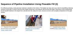
For efficient pumping, some granular material is needed in the mixture. The ballast can also serve as a dam for backfilling individual sections of the pipe, in which case the dam height should be in accordance with the final fill height. Placement of the hydraulically bound backfill material in the liquid form, directly from the ready mix truck, ensures an even and complete embedment of the pipe section. (Image: Placement of the unshrinkable fill … |
|
|
|
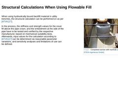
When using hydraulically bound backfill material in utility trenches, the structural calculation can be performed on as per [ATVA127]. In the process, the stiffness and strength values for the cover fill above the pipe crown, and the embedment at the side of the pipe have to be tested and verified by the respective manufacturer, based on mechanical suitability tests. Afterwards, input values for the calculation according to [ATVA127] can be determined … |
|
|
|
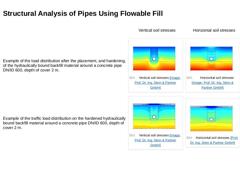
Vertical soil stresses |
Horizontal soil stresses |
|
Example of the load distribution after the placement, and hardening, of the hydraulically bound backfill material around a concrete pipe DN/ID 600, depth of cover 2 m. |
(Image: Vertical soil stresses) |
(Image: Horizontal soil stresses) |
|
Example of the traffic load distribution on the hardened hydraulically bound backfill material around a concrete pipe DN/ID 600, depth of cover 2 m. |
(Image: Vertical … |
|
|
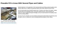
(Image: Hydraulically bound filling materials applied in a trench with several utility lines) Special attention in the application of the hydraulically bound filling materials applies when several utility lines or cables are positioned above each other within the trench zone. As the hydraulically bound backfill material sets, it hardens and clings to the pipes / cables located above the embedded sewer. During the setting process, the fill material … |
|
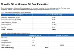
Costs savings are one of the most important aspects the contractor is looking for when selecting materials. The table below provides an average cost comparison between flowable fill and granular fill placement [[VancePool2008]]. (Table: Flowable fill vs. granular fill cost) |

|
(Image: Seitenverfuellung Einsparpotential Fluessigboden DN 350 - DN 700) Practical Example: Possible cost savings through the use of hydraulically bound backfill material (Image: Seitenverfuellung Einsparpotential Fluessigboden >DN 1200) DN 600 with base Backfilling cost using flowable fill: 0.7 m³ / m x 45.00 € / m³ = 31.50 € / m a) Excavated soil reused for backfilling |
Depth of excavation |
Cost of conventional backfilling |
Excavation savings |
|---|
|
T = … |
|
|
Various advantages make the use of hydraulically bound backfill materials a good alternative to the conventional backfilling of utility trenches with granular, unbound back-fill material: -
Prevention of typical installation errors/damage causes that can occur during the conventional installation procedure (e.g. insufficient backfilling and compaction in the spaces either side of the pipe, point loading of the pipe etc.)
-
Reduction of the trench widths …
|