|
|
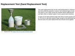
(Image: Replacement Test) |
The sand replacement test can be used productively in cohesive and non-uniformly grained or coarse, non-cohesive types of soil, into which a core cutter cannot be inserted without affecting the soil fabric (fine to medium types of sand, gravel-sand mixtures). In types of soil with particles larger than that of coarse gravel (2-5 in / 63 mm) or with pore spaces large enough to be penetrated by the test sand, the sand replacement … |
|
|
|
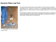
(Image: Dynamic Plate Load Test) |
The dynamic plate load test can be used in layers of soil with a dynamic modulus of deformation of EVd = 15 MN / m2 to 70 MN / m2. It is preferably suitable for mixed- and coarse particle, non-cohesive types of soil with a largest particle size of ≤ 0.02 in (0.63 mm). Provided that the material under test does not change and the tests are correlative, the dynamic plate load test by means of the so-called light drop … |
|
|
|
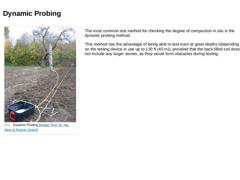
(Image: Dynamic Probing) |
The most common test method for checking the degree of compaction in situ is the dynamic probing method. This method has the advantage of being able to test even at great depths (depending on the testing device in use up to 130 ft (40 m)), provided that the back-filled soil does not include any larger stones, as they would form obstacles during testing. |
|
|
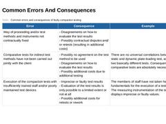
(Table: Common errors and consequences of faulty compaction testing) |

|
(Table: Common errors and consequences of faulty compaction testing (2)) |
|
|

|
Congratulations! You have successfully finished this module. Next, you will have the opportunity to review the newly acquired knowledge with an interactive questionnaire. You can, of course, still navigate back to any point in the modules if you wish to review a specific topic or subject. Stay curious! |
|
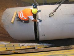
The installation of water and wastewater networks is carried out around the world to a large extent in open cut construction. This module focuses on all of the relevant information relating installation and alignment of the pipes, backfill compaction, alternative backfill materials, and the removal of the shoring. Upon the successful completion of this module, you will be able to: - identify and apply the main rules and regulations,
- ensure a high quality of workmanship on site,
- identify and assess construction errors, and
- optimise the installation process.
|
|
Today, supply and discharge lines are still predominantly installed by using the open-cut method: a trench is dug, the lines are installed. Under the protection of an embankment or sheeting and the trench is filled afterwards. In the face of the numerous disadvantages as well as the citizens' growing environmental consciousness in the future it is urgently necessary to take trenchless technology into account much stronger than until today as an alternative … |
|

|
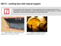
(Image: Simple hand shield - working face with natural support) |
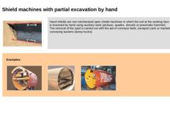
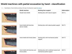
Hand shields are non-mechanised open shield machines in which the soil at the working face is loosened by hand using auxiliary tools (pickaxe, spades, shovels or pneumatic hammer). The removal of the spoil is carried out with the aid of conveyor belts, transport carts or tracked conveying buckets (dump trucks). |
|
|
|
Examples: |
(Image: Hand shield (external diameter 4672) with working … |
|
|
|
|
(Table: Classification of hand shields according to the type of working face support) |
|
|
|
|

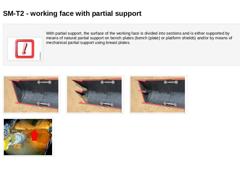
(Image: Attention!)With partial support, the surface of the working face is divided into sections and is either supported by means of natural partial support on bench plates (bench (plate) or platform shields) and/or by means of mechanical partial support using breast plates. (Image: Hand shield with breast plates - working face with mechanical partial support) (Image: Hand shield with benches (Bench shield) - working face with natural partial support) (… |
|
|
(Image: Attention!)
Shield machines with partial excavation by hand are predominantly used for: -
short jacking distances under 50 m
-
crossings of traffic ways
-
jacking of an extraordinary cross-section
-
groundwater-free soil or rock
|
|
|
|
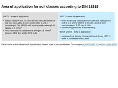
SM-T1 - areas of application: -
stable, cohesive soil, i.e. firm-stiff and very stiff cohesive soil (soil class LBM 2 and 3 and/or LBO 2 and 3 according to DIN 18319) with a compressive strength of approx. 1.0 N/mm2
-
Rock with uniaxial compressive strength ≥ 5 N/mm2 (classes FD 2 to 4 and/or FZ 2 to 4)
|
SM-T2 - areas of application: -
loose to densely compacted non-cohesive soil (classes LNE 1 to 3 and/or LNW 1 to 3) with a particle size concentration < …
|
|
|

|
|
|
(Image: Shield with fixed intalled excavation machine - working face with natural support (SM-T1)) |
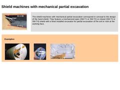
The shield machines with mechanical partial excavation correspond in concept to the design of the hand shield. They feature a mechanized open (SM-T1 or SM-T2) or closed (SM-T3 or SM-T4) shield with a fixed installed excavator for partial excavation of the soil or rock at the working face. |
|
|
|
Examples: |
(Image: Principles of support for open shield … |
|
|
|
|
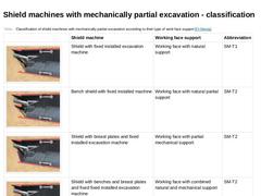
(Table: Classification of shield machines with mechanically partial excavation according to their type of work face support ) |
|
|
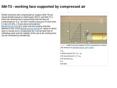
Shield machines with compressed air support (SM-T3) are closed shields based on shield types SM-T1 and SM-T2 in which the working face is pressurized with the flow off compressed air, e.g. "air with a positive pressure of more than 0.1 bar (10 kPa, 1.5 psi) above atmospheric" [ [DINEN12110:2014]] in order that the working chamber (defined in EN 12110 [ [DINEN12110:2014]] as "space in which work is carried out in compressed air") can be kept free … |
|
|
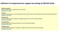
Working chamber:
Space in which work in compressed air is carried out.
[ [DINEN12110:2014]]
Air lock:
Pressure vessel with one or more chambers with access doors, which can be sealed and pressurized with compressed air.
[ [DINEN12110:2014]]
Material lock:
Air lock through which only material or equipment goes into or out of the working chamber.
[ [DINEN12110:2014]]
Personnel lock:
Air lock through which only persons go into or out of the working chamber. |
|
|
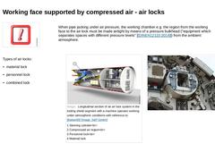
When pipe jacking under air pressure, the working chamber e.g. the region from the working face to the air lock must be made airtight by means of a pressure bulkhead ("equipment which separates spaces with different pressure levels" [ [DINEN12110:2014]]) from the ambient atmosphere. Types of air locks: -
material lock
-
personnel lock
-
combined lock
(Image: Longitudinal section of an air lock system in the trailing shield segment with … |
|

|
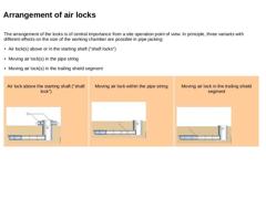
The arrangement of the locks is of central importance from a site operation point of view. In principle, three variants with different effects on the size of the working chamber are possible in pipe jacking: -
Air lock(s) above or in the starting shaft ("shaft locks")
-
Moving air lock(s) in the pipe string
-
Moving air lock(s) in the trailing shield segment
|
|
Air lock above the starting shaft ("shaft lock") (Image: Principle possibilities of arranging … |
|
|
|
Shield machines with compressed air support are used [Krets72] : -
In soil types where the lowering of the groundwater is not to be recommended on technical, ecological or economic reasons
-
In regions where the lowering of the groundwater could cause damaging subsidence
-
For jacking under waterways
-
For stabilizing the working face
|
|
|
|
The limits of use for jacking in compressed air are determined by [Krets72] : -
The pressure permitted by the compressed air ordinance [ELEXV97] of maximum 3.6 bar (360 kPa, 52.2 psi)
-
The air permeability of the subsoil
-
The minimum cover depth above the crown of the pipe (assessment of blow-out safety)
-
Economics, which can only be achieved with longer jacking lengths due to the high investment costs
-
The time and costs due to persons and materials …
|
|
|
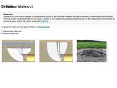
Blow-out:
A blow-out is the abrupt escape of compressed air out of the working chamber through loosened or remoulded subsoil when working under compressed air. In this case, it refers to the sudden escape (also blowing-out) of the supporting compressed air on the surface of the site or the water bed [DS853]. In general, there are two types of blow-outs [Baben99]: -
Gasometer blow-out
-
Erosion blow-out
(Image: Types of blow outs with reference to [FI-… |