|
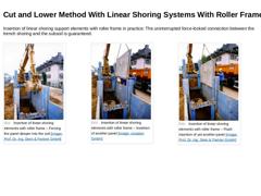
Insertion of linear shoring support elements with roller frame in practice: The uninterrupted force-locked connection between the trench shoring and the subsoil is guaranteed. (Image: Insertion of linear shoring elements with roller frame – Forcing the panel deeper into the soil) (Image: Insertion of linear shoring elements with roller frame – Insertion of another panel) (Image: Insertion of linear shoring elements with roller frame – Flush insertion … |

|
|

|
|
|
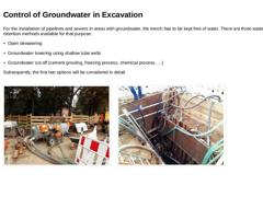
For the installation of pipelines and sewers in areas with groundwater, the trench has to be kept free of water. There are three water retention methods available for that purpose: -
Open dewatering
-
Groundwater lowering using shallow tube wells (well-points)
-
Groundwater cut-off (cement grouting, freezing process, chemical process, …)
Subsequently, the first two options will be considered in detail. (Image: Groundwater lowering using wells – Detail: … |
|
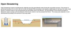
Open dewatering involves simultaneously collecting accruing groundwater water during the excavation process. This process is performed at about 20 in to 40 in (50 cm to 100 cm) ahead of the excavation, and requires stable types of soil (such as rock), coarse gravel or cohesive types of soil and generally low permeable soils to be effective. The groundwater can be directly pumped or allowed to seep to sumps at the boundaries of the trench, where it … |
|
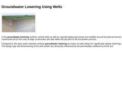
(Image: Groundwater lowering using wells) In the groundwater lowering method, vertical wells as well as required piping and pumps are installed around the planned trench or construction pit (in the case of large construction pits also within the pit) prior to the excavation process. Compared to the open water retention method, groundwater lowering by means of wells allows for significantly deeper lowerings. The design type and dimensioning of the well … |
|
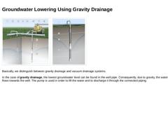
(Image: Installation of wellpoints for groundwater lowering using gravity drainage) (Image: Groundwater lowering using gravity drainage- mode of operation) (Image: Installation of wellpoints for groundwater lowering using gravity drainage) Basically, we distinguish between gravity drainage and vacuum drainage systems. In the case of gravity drainage, the lowest groundwater level can be found in the well pipe. Consequently, due to gravity, the water … |
|
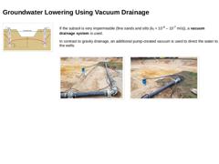
(Image: Example for groundwater lowering using vertical wells (well lowering)) If the subsoil is very impermeable (fine sands and silts (kf = 10-4 – 10-7 m/s)), a vacuum drainage system is used. In contrast to gravity drainage, an additional pump-created vacuum is used to direct the water to the wells. (Image: Groundwater lowering using vacuum drainage (deep well system) – Detail header pipe) (Image: Groundwater lowering using vacuum drainage (deep … |
|
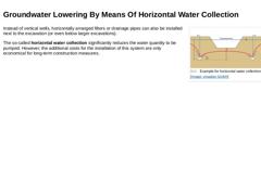
(Image: Example for horizontal water collection) Instead of vertical wells, horizontally arranged filters or drainage pipes can also be installed next to the excavation (or even below larger excavations). The so-called horizontal water collection significantly reduces the water quantity to be pumped. However, the additional costs for the installation of this system are only economical for long-term construction measures. |

|
|

|
Congratulations! You have successfully finished this lesson. Next you will have the opportunity to review the newly acquired knowledge with an interactive questionnaire. You can of course still navigate back to any point in the lessons if you wish to review a specific point or subject. Stay curious! |
|
The construction of sewers is still often carried out in the form of open cut construction. Depending on the design, this results in different pipe-soil systems with different external loads on the sewer. After completing this module, you will have a sound knowledge of: - rules and regulations;
- requirements for planning, tendering and construction of the pipeline zone, the shoring and the components and building materials;
- procedures for dewatering and
- process sequences of the open construction method.
|

|
The replacement of defective sewers in the current line run by the open cut method is basically comparable with the corresponding new sewer construction. As already mentioned in Abschnitt 5.4, this is the state of the technology and is here assumed to be known, so that mention will only be made of some peculiarities of the case under consideration in the following. A fundamental condition for the application of this process is the knowledge of the … |
|
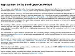
The semi open cut method, also called the semi open pipe jacking, is characterized in that the new man-accessible sewer, as with hydraulic pipe jacking (Abschnitt 5.4.3.3), is pushed through from a starting excavation to the target excavation. The removal of the soil and taking the sewer taken out of service is carried out from the surface with the protection of a bottom ring, open in the crown and with the assistance of a grab or excavator. For this … |
|
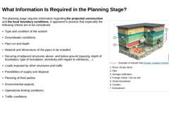
(Image: Example of subsoil risks) The planning stage requires information regarding the projected construction and the local boundary conditions. It appeared in practice that especially the following criteria are to be considered: -
Type and condition of the subsoil
-
Groundwater conditions
-
Pipe run and depth
-
Material and dimensions of the pipes to be installed
-
Securing of adjacent structures above- and below ground (spacing, depth of foundation, …
|
|
Information on the subsoil and its characteristics (soil parameters) as well as on groundwater conditions is required for the: -
Selection and structural calculation of the excavation support system (temporary sheeting, shoring, and bracing systems)
-
Selection and hydraulic calculation of groundwater retention measures (dewatering)
-
Selection and structural calculation of the pipes
-
Planning of measures for non-load-bearing or unstable subsoil
-
Specification …
|
|
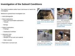
The subsoil conditions either have to be known or need to be investigated. Methods for geotechnical investigation are: -
Aerial photographs
-
Direct explorations
-
Given and examinable explorations
-
Trial pits
-
Borings
-
Indirect explorations
-
Probings
-
Geophysical methods
-
Laboratory tests
-
Soil samples
-
Samples of rock and rock material
-
Water samples
-
Field trials in soil and rock
(Image: Direct explorations – Trial pit) (Image: Direct explorations – … |
|
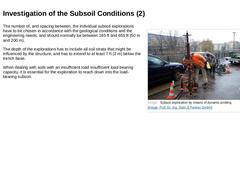
(Image: Subsoil exploration by means of dynamic probing) The number of, and spacing between, the individual subsoil explorations have to be chosen in accordance with the geological conditions and the engineering needs, and should normally be between 165 ft and 655 ft (50 m and 200 m). The depth of the explorations has to include all soil strata that might be influenced by the structure, and has to extend to at least 7 ft (2 m) below the trench base. |

|
|
|
The extent of the assessment regarding the degree of aggressivity of different types of water, soil and gas is significantly influenced by the pipe material. Examples for the requirements for the evaluation of the corrosion probability of metallic material can be found in [[NACE SP0502-2008]] and [ [DIN50929-3]]. Cement-bound material can be detrimentally affected by different types of water and soil, if these contain the following components: |
|
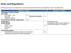
Planning and execution of utility trench construction should follow the rules and regulations shown in the table below. |
Planning / “Theory” |
Execution / “Practice” |
|---|
|
STANDARDS / REGULATIONS: ATV DVWK *ATV DVWK – A 127 *EN 1295 *Material standards |
>>> |
Structural Calculation |
>>> |
*CONSTRUCTION *Occupational health & safety regulations *OSHA 1926 Subpart P- Excavations |
|
SITE-SPECIFIC LIMITING CONDITIONS |
>>> |
|
STANDARDS /
REGULATIONS: *EN 1610 *DWA – A 139… |
|

|
As a part of the execution planning, a detailed design of the sewer lines and structures is prepared, and includes the following components: -
Survey maps that show the position of the entire construction measure (scale min. 1:5,000)
-
Layouts (scale min. 1:1,000 / in urban areas min. 1:250)
-
Longitudinal sections/gradient diagrams (scale min. 1:1,000 for the lengths and min. 1:100 for the heights, inclusive of information on subsoil explorations and …
|
|
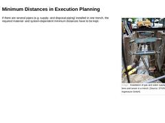
(Image: Installation of gas and water supply lines and sewer in a trench ) If there are several pipes (e.g. supply- and disposal piping) installed in one trench, the required material- and system-dependent minimum distances have to be kept. |
|
The following information includes some of the details required by, and for, the successful execution of work: -
Location of the construction site
-
Ambient conditions
-
Access possibilites, condition of the access road as well as any limitations in its use
-
Already existing, or in close vicinity existing supply- and disposal piping
-
Disposal route (re-use or elimination) for debris and excavated soil
-
Special stipulations for the protection of residents …
|
|
Where required, the limiting values for deviations from the determined lateral and vertical position of the pipe are to be specified. They depend primarily on the following factors: -
Hydraulics
-
Drainage method
-
Pipe run (position and gradient)
-
Construction method
-
Dimensional accuracy of the pipes
-
Operation and maintenance of the sewer network
|