Stress corrosion cracking of polyethylene - practical examples of steel pipe coatings
Oct 05, 2007
This paper describes various forms of stress corrosion cracking in polyethylene and discusses them on the basis of practical examples of polyethylene steel pipe coatings. The study was made possible by targeted localization of coating holidays using various methods of cathodic corrosion protection (CCP) and the following subsequent examinations of the damages and especially the change of material properties.
The stress cracking phenomena detected during pipeline inspections caused us to look more closely into this specific form of polyethylene damage. The reasons for crack formation in polyethylene are many and varied, including mechanical impact, the effect of wetting agents and also aging-induced embrittlement of the material. Investigation of the damage cases revealed that conventional creep tests cannot provide a valid prognosis of the long-time service behaviour of polyethylene components. When assessing damage events of this kind it has to be considered that the strain acting on the material combination of polyethylene and steel remains relatively low under service conditions in gas and water distribution systems. Stresses and the resultant cracks, even in the case of aging- induced embrittlement, are primarily attributable to impermissible local point loads or outside interference. Even so, it would be desirable to be able not only to determine the creep resistance of polyethylene by tests but also to improve it with a view to the intended application and service conditions.
Introduction
The use of polyolefines is well established in the production of pipes for the transportation of drinking water and wastewaters and/or media and gases hazardous to water. Polyethylene is used both as a pipe material and also for coating steel and ductile iron pipes.
The essential advantage of this material lies in its chemical resistance, which allows its application in soils of all classes, including severely aggressive environments. However, chemical resistance must not be confused with corrosion resistance. DIN EN ISO 8044 defines corrosion as the interaction of a material with its environment in a process that changes the mechanical properties and may eventually lead to failure of the affected component. The interaction can be chemical, physical or electrochemical in nature. This definition applies not only to metals, but also to non-metallic materials, such as plastics or cement-bound materials. Very often, the term corrosion is wrongly used in a restricted sense, referring to the specific case of electrochemical corrosion in metallic materials [1]. Especially in case of plastic materials it has to be considered, that stabilization against heat or light aging and any modification to their chemical composition geared to improving their resistance to stress corrosion cracking, are all basically measures of corrosion protection.
In embrittled polyethylene pipe or coating material, crack initiation occurs in sites subject to additional external stresses such as point loads or point supports [2, 3]. Another form of stress corrosion cracking is attributable to the effect of crack-promoting media such as wetting agents. The essential difference between these two mechanisms is that cracking under the effect of a wetting agent already starts under stresses far below the allowable proof stress of the material. Aginginduced embrittlement in a material not exposed to wetting agents will lead to cracking only if the sum of all stress components exceeds the material's allowable stress level. It must be considered, however, that aging gradually changes a material's fracture mechanical behaviour, e.g. in terms of elongation to break. On the other hand, wetting agents can cause damage even in non-aged materials, depending on the molecular structure of the polymer. This type of damage to polyethylene coatings on steel pipes has been widely reported. Unfortunately though, the distinct lack of background information in the literature has frequently given rise to irritation in discussions with distribution companies. This article presents and discusses the basic mechanisms of stress corrosion cracking in polyethylene using practical examples of steel pipe coatings.
Polyethylene coating – a historical review
The use of polyethylene for steel pipe coating is state of the art. A substantial advantage of this material is its chemical resistance, which allows its application in soils of all classes, including severely aggressive environments. Introduced as an anti-corrosion coating for buried steel line pipe in the 1950s, polyethylene has meantime completely replaced the former standard coating material, bitumen, chiefly – but not exclusively – due to its significantly higher electrical resistivity. Today, a single cathodic corrosion protection system can reliably monitor and protect pipeline sections of over 100 km.
The first polyethylene coatings were applied using a sintering technique. To start with, the pipe was steel grit shot blasted to bright metal. In the coating facility, the pipe was rotated while polyethylene powder was spread on its surface, which was heated to approximately 300 °C. On contact with the steel surface, polyethylene powder fuses into a homogeneous coating. Compared to the later coatings applied by blown film extrusion, the shortcoming of these powder coatings was their poor adhesion and elongation at break, because sintered polyethylene has a more brittle behaviour than extruded polyethylene.
Extruded plastic coatings, applied by either blown film extrusion or the extrusion wrapping process, were first introduced in the mid 1960s. Initially, they consisted of two layers, namely an adhesive agent and a polyethylene layer. The mid-1980s saw the launch of three-layer coating systems with an additional primer based on epoxy resin. These practice-oriented systems achieve high adhesive strength at room temperature and can easily be cut back in the field as required by simply heating up the pipe ends. All polyethylene types – i.e. low (LDPE), medium (MDPE) and high density polyethylene (HDPE) are used, with MDPE and HDPE preferred for higher service temperatures. Polypropylene coatings have not established themselves to the same extent and are predominantly used in special cases, such as trenchless pipe-laying projects.
Standardization of polyethylene coatings for steel pipe
State-of-the-art steel pipe coating is done on the basis of the most current version of DIN 30670, which was published in 1991. Depending on the pipe dimensions, the coatings are applied to a thickness of between 1.8 and 3.0 mm. For special applications, the standard coating thickness can be increased by 0.7 mm (Table 1).
| Polyethylene coatings acc. to DIN 30670 | |||
|---|---|---|---|
| Diameter (DN) | Coating thickness | ||
| Type N | Type V | ||
| ≤ 100 | 1.8 mm | 2.5 mm | |
|
> DN 100 ≤ DN 250 |
2.0 mm | 2.7 mm | |
|
> DN 250 < DN 500 |
2.2 mm | 2.9 mm | |
|
≥ DN 500 < DN 800 |
2.5 mm | 3.2 mm | |
| ≥ DN 800 | 3.0 mm | 3.7 mm | |
Table 1: Layer thicknesses in polyethylene coatings according to DIN 30670
The requirements of the various editions of this standard for polyethylene coatings are closely linked to technical advances in the input materials and the coating process itself. In 1974, DIN 30670 was published as a draft standard for polyethylene coatings of buried steel pipe. In the first revised edition, the minimum peeling resistance of polyethylene coatings was increased from 15 to 35 N/cm strip width. These minimum requirements were supplemented in 1991 by a rise in the test temperature. Here, a differentiation was made between normal coating (N) for service temperatures of up to 50 °C and special coating (S) for up to 70 °C. The minimum peeling resistance at 50 °C was specified as 15 N/cm strip width for the normal coating and 25 N/cm strip width for the special coating (S).
Besides the demands on process-related product properties, the requirements made on the corrosion resistance of polyethylene were continuously increased. The 1974 version specified a combined heat- and light-aging test. The temperature measured using a black standard thermometer was around 60 °C. The exposure time to xenon-arc light was 800 hours. The gauge of aging was determined to be the melt index, with a maximum allowable variation from the initial value of 25 %. The 1980 version of DIN 30670 separated this combined test into two units. The resistance to heat aging was tested at 100 °C over a period of 2400 hours. The same period was specified for the light aging test, in conjunction with a maximum allowable black standard temperature of 45 °C. In both cases, the maximum allowable melt index variation from the initial value was 35 %. The current version of DIN 30670, published in 1991, stipulates an energy input of 7 GJ and a black standard temperature of 65 °C for the light-aging test. The requirements on the heat resistance of polyethylene have remained unchanged since 1980, while an exposure period of 4800 hours has been defined for the newly introduced special coating thickness.
At a European level, PE coating standardization activities have been discontinued for the sintered and the extruded three-layer PE coating types. Now the only PE coating specified in a European standard is the two-layer coating, which was taken out of production in Germany 20 years ago. The findings presented in this article show that the aging tests laid down in the standards for the longtime properties of polyethylene will have to be viewed more critically in the future.
Stress corrosion cracking in polyethylene coatings of steel pipes
Today's approach to stress corrosion cracking in polyethylene coatings of steel pipes for standard applications in water and gas distribution systems merely considers the coating types featuring the low peeling resistance of the early editions of DIN 30670, i.e. sintered and two-layer coatings which were used especially up until 1985. However, we must differentiate between three types of cracking in polyethylene coatings of steel pipes:
- Mechanical damage
- Cracking due to embrittlement
- Secondary cracking initiated at the sites of coating holidays in pipelines with cathodic corrosion protection.
The resulting stress generated two approximately 1-metre cracks which propagated to either side of the coating holiday. The steel pipe remained unaffected thanks to its high mechanical strength. The polyethylene coating is a two-layer system with a bituminous adhesive of the type used as standard in the 1970s. The peeling resistance and the bonding strength of the adhesive were significantly inferior to the systems used later.
The questions linked to polyethylene aging and, especially, to the verification of its suitability for the intended application have frequently been raised in the context of other polyethylene products, too. At the Wiesbaden Plastic Pipe Conference 2004 (Wiesbadener Kunststoffrohrtage 2004), for example, experts reported on comparable results with pipes made in both LDPE- and HDPE-base materials. Despite the verified acceptance of the materials' elongation at break, some of these between 20- and 30- year-old pipes had passed the internal pressure creep test [4] without objection. This means there is no reason at all to believe that these pipes would not have passed the internal pressure creep test at the time of their manufacture. All the more amazing is the embrittlement of which there was clear evidence.
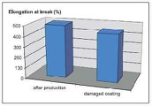
The decisive contradiction, however, is the recognizable corrosion problem that affects the fracture mechanical properties on the one hand, and, on the other, the assumed serviceability of the pipe, based on the fact that it has passed the internal pressure creep test. This contradiction can be resolved simply by exposing service-aged polyethylene specimens to heat. A mere 24-hour exposure to 60 °C suffices to raise the elongation of service-aged polyethylene from a modest 25 % to over 400 % (Fig. 4). The elongation at break does not follow the timetemperature behaviour of the material strength tested in creep tests. The elongation at break decreases much faster under praxis conditions. With the decrease of elongation at break also the crack mechanism of the polyethylene changes. Hence the direct transfer of creep test results to the service life of buried polyethylene components at lower temperatures and partly unknown effects of media in the soil is absolutely impermissible.
This raises the question of how, from today's point of view, the aging resistance of polyethylene can be tested with results that are both meaningful and relevant to practical requirements. Considering that the polymer structure, and with it the aging behaviour, of polyethylene obviously changes at higher temperatures, the value of such tests must be questioned from the point of view of quality alone. This issue is the subject of current investigations and may call for the use of new analytical methods, which were not available at the time when today's standard exposure tests were developed [5].
 Secondary cracking initiated at the sites of coating holidays in pipelines with cathodic corrosion protection
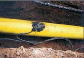
Apart from the well-known stress corrosion cracking types described above, there have been cases of cracking in polyethylene whose origin could not be attributed to a combination of mechanical stresses and material embrittlement. In phenomenological terms, this damage type can be described as long-running cracks in a coating whose elongation at break nevertheless still corresponds to the as-manufactured condition (Figure 5 and 6).
The external conditions observed with this type of stress corrosion cracking were always the same and always occurred as a combination of the following marginal conditions:
- The pipes are coated with a two-layer system.
- The crack goes through the coating, right through to the steel surface.
- The coating holiday exhibits notch tips, e.g. in the form of knife cuts.
- The pipeline features cathodic corrosion protection.
The complex mechanistic interactions of this type of stress corrosion cracking have been verified in numerous test series. The most important test methods and results will be outlined in the following sections.
 Test results and discussion
The polyethylene-coated pipe specimens were manufactured under standard production conditions. For the stress cracking investigations, the polyethylene coating was cut through to the steel surface and completely removed over a length of 40 mm. The sharp-edged carpet knife used for this purpose was fitted with a new blade after each cut. On the polyethylene-coated segment, a piece of PVC pipe was positioned around the site of the cut as a vessel for the test solution (Figure 7). The specimens were exposed to this solution at room temperature. They were checked daily and the time of crack initiation was documented.
In addition to the 5 % wetting agent solution (Igepal, see Bell Test, ASTM 1693), a 3 % NaCl solution and, as an alternative, the synthetic soil solution according to von Baeckmann [6] were used as test media under cathodic corrosion protection conditions. The synthetic soil solution was made up of the following components:
- 17 mg/l magnesium sulfate (MgSO4 · 7 H2O)
- 733 mg/l calcium chloride (CaCl2 · 2 H2O)
- 430 mg/l calcium sulfate (CaSO4 · 2 H2O)
- 210 mg/l sodium hydrogen carbonate (Na2 HCO3).
To simulate the service conditions of a cathodically protected pipeline, the steel surface was polarized to –1.5 volt with the aid of a calomel reference electrode.
One of the key objectives of this investigation was to determine the effects of influencing parameters such as the coating structure and the polyethylene types used in the past. Figure 8 shows the most important findings of the relevant laboratory tests.
Two different coatings systems were included in the investigations. These were the twolayer system with an adhesive based on polyacrylic resin and a polyethylene top layer, and the three-layer system consisting of an epoxy resin primer, an acrylic acid / acrylate modified PE copolymer adhesive, and a top layer of polyethylene. In addition, three LDPE types with different melt indices were used. The decreasing melt index in this case is mainly due to the increasing chain length of the polyethylene types used. The time of crack initiation in the presence of a wetting agent and on exposure to the salt solution in combination with cathodic corrosion protection correlates only for the two-layer PE coatings. These systems clearly show that the resistance to stress corrosion cracking increases with increasing chain lengths (Fig. 8). In the case of three-layer systems, no sign of stress corrosion cracking was observed even after 700 days' exposure and irrespective of the polyethylene type used. When evaluating the test results it should be borne in mind that neither the two-layer system with the polyethylene type in the melt index range of 0.3 to 0.4 nor the three-layer system with the polyethylene type in the melt index range of 0.6 to 1.0 have ever been used in a real project.
A glance at practice confirms the laboratory results. All the damage events reported over the years have been carefully documented in terms of the time or period of production, crack length and elongation of the polyethylene coating.
In the mid-eighties, the system that is still standard practice today – the three-layer PE coating with additional epoxy resin primer – was introduced in Germany. Since the change-over to the three-layer system with polyethylene types in the melt index of 0.3 to 0.4, no more damage events involving stress corrosion cracking of the described nature have occurred.
Influence of the chemical composition of the medium
Attempts have of course been made in the past to detect such damage in polyethylene coatings by means of close interval potential survey (CIPS). However, the search proved to be extremely difficult. Stress corrosion cracking was encountered significantly less frequently than expected, because it will develop only if specific various marginal conditions occur in conjunction.
It was thus proved that alkalinity together with cathodic polarization as well as the soil properties in the area of a coating holiday are major factors in the type of stress corrosion cracking investigated here. In salt solution, sodium hydroxide is generated primarily at the site of the coating holiday while, in the case of the synthetic soil solution, the buffer effect of hydrocarbonate prevents high ph-values and thus stress corrosion cracking.
Mechanistic considerations
Stress corrosion cracking under the effect of wetting agents
Stress corrosion cracking phenomena are not limited to polyethylene coatings of steel pipe. They have been observed in all products heat shaped from plastic materials. As the designation indicates, the basic prerequisite for the occurrence of stress cracking is the presence of stresses. In the case of heat shaped plastic materials, stresses are generated during production and/or under service conditions under the combined effect of high thermal expansion and poor thermal conductivity. At least part of these stresses will remain in the component. The particularities of stresses in components, especially in polyethylene components, have been discussed in previous reports [7]. A generally accepted description of the stress cracking mechanism is provided by the particle theory (Figure 11).
Given that crystalline regions (particles, crystallites) are primarily held together at the boundaries by entangled molecular chains (crystal bridges), the presence of wetting agents and stresses will cause this structure to expand or swell. At this stage, expansion is still reversible. However, if there is a notch, cracks may be initiated by disentangled molecular chains. Crack initiation and the speed of crack propagation will be a function of the chain lengths, local stresses in the notch tip, and the type of wetting agent used. This form of cracking is triggered by a chemical reaction, i.e. a diffusion controlled process based on physical laws. It falls under the category of environmental stress cracking (ESCR) and requires the following boundary conditions:
- Materials susceptible to stress cracking
- A holiday geometry with notch effect
- Presence of wetting agents
- Presence of stresses
While the susceptibility to stress cracking in the materials used has been clarified both in the laboratory and in practice, the other boundary conditions deserve special consideration.
Apart from major impacts through the likes of an excavator tooth or an accidental blow with a pick, normal work such as the installation of service connections has provided ample opportunities for damage to the coating in the form of holidays with a notch effect. Although technical rules for the installation of service connections stipulate expressly that the coating be removed with a single circular cut, it happens very frequently that four cuts are made (Figure 12) for this purpose. Given subsequent thermal damage by the burner normally used for loosening the top layer, possibly in combination with inappropriate field coating, the end points of these cuts serve as crack initiation sites for the kind of stress damage discussed here.
To understand the generation of the wetting agents required for the occurrence of stress cracking, it is necessary to take a closer look into the effect of cathodic corrosion protection on a coating defect which penetrates to the steel surface. The most important electrochemical reactions to be considered in the area of coating holidays in a cathodically protected pipeline are shown in Figure 13.
The steel pipe to be protected is electrically coupled to the sacrificial anode which consists of a less noble metal. Due to the difference in potential, an excess of electrons is generated in the steel, which prevents its iron content from reacting with the soil and dissolving. At the site of a coating holiday, the excess electrons promote the reaction of oxygen into hydroxide as a cathodic partial reaction. The anodic partial reaction is shifted to the sacrificial anode which is installed at a remote site. A properly functioning cathodic protection system will indicate coating holidays by intensive alkali hydroxide formation which, in turn, leads to a rise in the pH value of the soil medium. With a two-layer system, a high pH value led to local saponification of the adhesive and hence to the generation of wetting agents (alkalis) in the area of the steel surface. This mechanistic approach is confirmed by the correlation of the laboratory results for two-layer coating systems under cathodic polarization in salt solution and in the presence of wetting agents.
The separation of the steel surface and the adhesive by means of the epoxy resin primer effectively prevents the formation of a wetting agent, which is why such forms of stress cracking are unknown with three-layer coating systems.
The described effect of cathodic corrosion protection must not be allowed to obscure the fact that the stress cracking phenomena discussed here are always caused by a damaged coating. In individual cases, corrosion was observed under the effect of impermissible external current. Depending on the size of a coating holiday, an increase in its surface due to cracking should rather be assessed as positive. Weightloss in the area of the holiday will be directly proportional to the current discharge. The smaller a holiday site becomes under the effect of external current, the more severe the metal wastage will be. Provided that the criteria laid down in the technical rules for cathodic corrosion protection are met, corrosion will be prevented in the base material as well as at the sites of the coating holiday and the crack. In addition, holiday sites in the polyethylene coating can be easily detected via cathodic corrosion protection. Without this possibility of identifying and recording the condition of a buried pipeline it would have been impossible to obtain the findings presented here.
For an assessment of stresses in polyethylene coatings, another glance at the damage statistics will be helpful. Figure 14 shows an evaluation of damage events in terms of crack lengths measured in the polyethylene coating. Most of the cracks remain within the length range of up to 2 metres. Further evaluation of the damage cases in relation to the pipe dimensions reveals a significant increase in the number of long cracks for pipe sizes greater than DN 200 (Fig. 14). Obviously the stresses are higher in these pipes than in the smaller pipe sizes.
Looking at the production conditions, the origin of residual stresses in polyethylene coatings is quite clear. The pipe cooling rate is decisively governed by the pipe wall thickness and diameter as well as by the speed of the coating process. The different coefficients of thermal expansion of steel and polyethylene also play a special role. Residual stresses are apparently most marked in the larger pipe sizes.
Conclusions
This paper looked at stress corrosion cracking in polyethylene as exemplified in steel pipe coatings. In addition to the well-known forms of crack formation due to embrittlement, e.g. through light or heat aging and mechanical coating damage, a third form of stress cracking damage is described which, as a secondary damage, presupposes the existence of a holiday site in the polyethylene coating of a steel pipeline in conjunction with specific boundary conditions, which must occur together to cause cracking. In mechanistic terms, this damage type corresponds to stress corrosion cracking in the presence of wetting agents. A pipeline with cathodic corrosion protection will not be at risk from this damage if all the protection criteria are fulfilled [8]. In Germany, only coating systems which prevent the occurrence of this type of stress cracking have been manufactured for the last 20 years.
Stress cracks observed in embrittled polyethylene coatings are attributable to local loads exceeding the allowable proof stresses and elongation at break. Without such impermissible local loads, this risk does not exist, because the material combination of polyethylene and steel is not exposed to such strain under pipeline operating conditions. From a functional aspect, steel pipe coatings are required to act as a barrier to corrosive components in the soil. The coating does not contribute in any way to the static behaviour of this material combination.
The results presented here show that longtime statements based on tests must be viewed critically, especially where material aging is concerned. For the creep behaviour in case of polyethylene pipes it was shown that the material strength shoes a good correlation to the Arrhenius effect. The suitability of polyethylene is not governed by its allowable stress level alone. The entirety of its mechanical properties has to take in account. The elongation at break does not follow the time-temperature behaviour of the material strength. The aging-induced drop in the elongation at break under the service conditions of buried pipelines after twenty to thirty years of service is not detected. The structure of polyethylene changes with higher test temperatures and therefore the aging behaviour of polyethylene.
Testing of polyethylene to stress cracking represents a special problem. At present, there is no test that fully covers all the aspects relevant to practical conditions. The current version of the DIN 30670 refers as follows to polyethylene coatings of steel pipelines:
“The responsible technical committee agreed that it would be useful to determine the tear resistance of polyethylene coatings. To this end, a number of studies have been conducted under various test conditions, but it has not been possible to obtain practical, reproducible results. Work in this regard is continuing.”
As things stand today, this statement is still valid. The investigation described here could serve as a basis for a practice-oriented test for polyethylene coatings in which cathodically polarized specimens with cuts in the coating are exposed to a salt solution. For the crack formation in presence of wetting agents, it must be borne in mind, however, that the results can only be meaningful for polyethylene components whose microstructure and/or fracture mechanical characteristics have not yet changed due to aging processes. Cracking under the effect of a wetting agent is not related to a material's aging process but exclusively to the properties of the polymer structure at the time of exposure. Any evaluation of such test results must consider the change in the polymer structure with increasing temperatures and the concomitant change in its aging behaviour. Under the effect of a wetting agent, the stress required for crack initiation is far below the allowable proof stress of a material. Here, the kinetics are largely determined by diffusion processes and gives no information about chemical aging and the related embrittlement of the material.
The examples of stress corrosion cracking and the underlying causes presented here clearly show that further research into these issues is urgently required. There are, above all, no tests by means of which significant statements can be obtained as to the fitness of polyethylene components for a given application, especially with regard to their longterm behaviour under the service conditions of buried pipelines.
Literature
[1] Schmitt, G.: Der Korrosionsbegriff bei nichtmetallischen Werkstoffen; Materials and Corrosion 55 (2004), pp. 367-372
[2] Kiesselbach, G.: Sicherheit und Nutzungsdauer erdverlegter PE-Druckrohrleitungen. Teil 1: Rohrversagen bei Punktlagerungen? gwf Wasser/Abwasser (2004) No. 1
[3] Kiesselbach, G.: Sicherheit und Nutzungsdauer erd
[4] Krietenbrink H.; Kloth, R.: 100 Jahre Nutzungsdauer von PE- Rohrsystemen in der Wasserversorgung; 3R international 43 (2004) No. 10, pp. 576 ff.
[5] Blümich, B.; Casanova, F.; Buda, A.; Kremer, K.; Wegener, T.: Anwendungen der mobilen NMR zur Zustandsbewertung von Bauteilen aus Polyethylen; 3R International 44 (2005), pp. 349- 354
[6] von Baeckmann, W.G.: Kathodische Korrosion von Blei im Erdboden; Werkstoffe und Korrosion 20 (1969), pp. 578-583
[7] Kocks, H.-J.: Prüfgrundlagen und Stand der Normen für Stahlleitungs- und Kunststoffrohre - Regelwerke mit zweierlei Maß?; Rohrleitungen eine unendliche Geschichte?, Vulkan Verlag Essen, 2004 (Publication series from the Institute for Pipeline Construction at Oldenburg University of Applied Sciences; Vol. 28)
[8] Schwenk, W.: Bemerkungen zur Abschätzung von Umhüllungsschäden erdverlegter Stahlrohre aus Potentialgradienten-Messungen; 3R international 33 (1994), pp. 328-337
More News and Articles
May 26, 2025
News
Kanalgipfel 2025: Smart Processing – mit KI-Technologien von der Kanalinspektion bis zur Sanierungsstrategie
Die Entwässerungssysteme unserer Städte sind ein wesentlicher Bestandteil des kommunalen Anlagevermögens. Die große Zukunftsaufgabe, …
May 12, 2025
News
Kanalgipfel 2025: Stand der Kanalsanierung in Deutschland – Eine kritische Betrachtung
Die Entwässerungssysteme unserer Städte sind ein wesentlicher Bestandteil des kommunalen Anlagevermögens. Die große Zukunftsaufgabe, vor der viele Kommunen …
Aug 28, 2024
News
ITpipes Secures $20M to Transform Water Infrastructure Management
ITpipes announced it has secured $20 million in equity financing from Trilogy Search Partners and Miramar Equity Partners.
Known for its trusted and user-friendly platform, ITpipes …
Aug 26, 2024
News
Professor Dr.-Ing. Dietrich Stein
With deep sadness we announce the loss of our founder and partner Prof Dr Dietrich Stein at the age of 85.
Engineers around the globe are thankful for his dedication to the inventions in the fields of sewers, …
Aug 26, 2024
News
PPI Releases New Installation Guide for PE4710 Pipe
PPI’s MAB-11-2024 Covers HDPE Water Pipelines Up to 60-in. Diameter and 10,000-ft Long Pulls
Developed by the Municipal Advisory Board (MAB) – and published with the help of the members of the …
Aug 23, 2024
News
Faster wide-scale leak detection now within reach
Mass deployment of connected leak loggers is being made possible by the latest technology, writes Tony Gwynne, global leakage solutions director, Ovarro
Water companies in England and Wales are …
Aug 21, 2024
News
Kraken awakens customer service potential in water
The innovative customer service platform Kraken has made a successful transfer from energy to water. Ahead of their presentation at UKWIR’s annual conference, Portsmouth Water chief executive …
Aug 19, 2024
News
Predicting the toxicity of chemicals with AI
Researchers at Eawag and the Swiss Data Science Center have trained AI algorithms with a comprehensive ecotoxicological dataset. Now their machine learning models can predict how toxic chemicals are …
Aug 16, 2024
News
Goodbye water loss: Trenchless pipe renewal in Brazil
Pipe renewal in Brazil
How do you stop water loss through leaks in old pipe systems without major environmental impacts and restrictions? The answer: with trenchless technology, or more precisely …
Aug 14, 2024
Article
Impact of high-temperature heat storage on groundwater
In a recently launched project, the aquatic research institute Eawag is investigating how the use of borehole thermal energy storage (BTES) affects the surrounding soil, the groundwater …
Aug 12, 2024
News
Watercare completes East Coast Bays sewer link
Watercare has successfully finished the final connection on the East Coast Bays link sewer at Windsor Park in New Zealand.
Much of the East Coast Bays sewer link was installed using horizontal directional …
Aug 09, 2024
Article
Innovative water solutions for sustainable cities
Cities need to become more sustainable and use their water resources more efficiently. Managing water in local small-scale cycles is one possible solution. A new white paper by Eawag, the University …
Contact
Salzgitter Mannesmann Line Pipe GmbH
In der Steinwiese 31
57074 Siegen
Germany
Phone:
+49 271 691-0
Fax:
+49 271 691-299
