|

| (Image: Attention!)
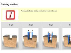
Prerequisite for the sinking method: soil must not flow out | | Step 1 (Image: Installation of edge-supported trench lining systems (ES) in the sinking method - Working step 1: Excavation corresponding to local conditions as far as possible)
| Step 2 (Image: Installation of edge-supported trench lining systems (ES) in the sinking method - Working step 2: Insertion, stepped excavation (maximum of 0.50 m) and sinking the trench lining system)
|
|
|

| (Image: Pros and cons) |
|
Advantages of lining systems: - can be used in almost all soils
- can be used several times without modification
- short installation time due to mechanical installation and removal
- no vibrations, low noise emissions
|
|
Disadvantages of lining systems: - limited applicability in the region of crossing lines (additional measures required)
- lifting devices required
- utilization only above the, possibly lowered, groundwater level
|
|
|

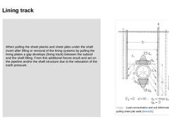
When pulling the sheet planks and sheet piles under the shaft invert after filling or removal of the lining systems by pulling the lining plates a gap develops (lining track) between the subsoil and the shaft filling. From this additional forces result and act on the pipeline and/or the shaft structure due to the relocation of the earth pressure. |
(Image: Load concentration and soil deformation when pulling sheet pile walls [Hornu91]) |
|
|

|
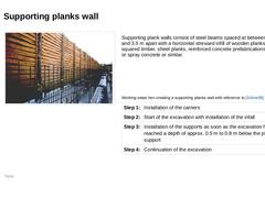
(Image: Supporting planks wall [FI-Emun])
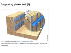
Supporting plank walls consist of steel beams spaced at between 2.0 m and 3.5 m apart with a horizontal stressed infill of wooden planks, squared timber, sheet planks, reinforced concrete prefabrications, insitu or spray concrete or similar. (Table: Working steps hen creating a supporting planks wall with reference to [Schne95] [FI-Steina]) |
|
|

(Image: Supporting planks wall) |
|

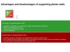
| (Image: Pros and cons) | | Advantages of supporting planks walls: - adaptable to obstacles such as pipelines, shafts, old foundations and others
- usable in nearly all types of soils
- construction components re-usable
- economic efficiency
| | Disadvantages of supporting planks walls: - soft lining, danger of subsidence for neighbouring structures or traffic areas
- due to limited transport lengths of the beams not usable for arbitrary depths (at best extendable …
|
|
|

|
|

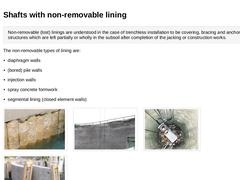
Non-removable (lost) linings are understood in the case of trenchless installation to be covering, bracing and anchoring structures which are left partially or wholly in the subsoil after completion of the jacking or construction works. The non-removable types of lining are: (Image: (Bored) pile wall) (Image: Shaft securing with spray … |
|

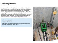
In perpendicular trenches (slats) 0.4 m to 1.20 m width, 2.0 m to 5.0 m long that are created by special diaphragm wall grabs, prefabricated reinforcing cages are placed and concrete is poured. The collapse of the walls is prevented by a filling with a supporting fluid with thixotropic properties (Bentonite suspension). Horizontal concrete sections are limited by means of formwork pipes or similar. The concreting process can be carried out in-line … |
|

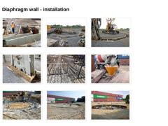
(Image: Construction of the baffle wall (reinforced concrete) on both sides of the slot for the diaphragm wall excavator) (Image: Completed baffle wall for the diaphragm wall excavator) (Image: Excavation of the diaphragm wall - Diaphragm wall excavator) (Image: Detail of diaphragm exhibitor) (Image: Reinforcement cages for the diaphragm wall) (Image: Concreting the diaphragm wall) (Image: Chipping of the top of the baffle and diaphragm wall, exposing … |
|

|
(Image: Attention!)
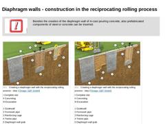
Besides the creation of the diaphragm wall of in-cast pouring concrete, also prefabricated components of steel or concrete can be inserted. |
|
|
|
(Image: Creating a diaphragm wall with the reciprocating rolling process - step 1) |
(Image: Creating a diaphragm wall with the reciprocating rolling process - step 2) |
|
(Video: Excavator in diaphragm wall operation) |
|

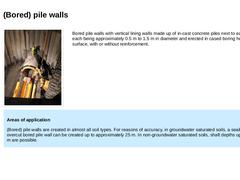
(Image: Starting shaft with bored pile wall) Bored pile walls with vertical lining walls made up of in-cast concrete piles next to each other, each being approximately 0.5 m to 1.5 m in diameter and erected in cased boring holes from the surface, with or without reinforcement. |
|
Areas of application (Bored) pile walls are created in almost all soil types. For reasons of accuracy, in groundwater saturated soils, a sealing overcut bored pile wall can be … |
|
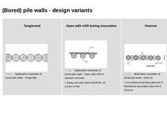
|

|
Tangierend
(Image: Application examples of bored pile walls - Tangential) |
Open with infill during excavation
(Image: Application examples of bored pile walls - Open with infill of sprayed concrete) |
Overcut
(Image: Application examples of bored pile walls - Overcut) |
|
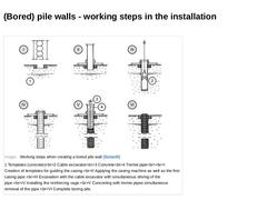
|

(Image: Working steps when creating a bored pile wall [Balda88]) |
|

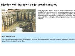
| (Image: Open columns during excavation [FI-Brück]) | With jet grouting the soil structure is loosened by means of a jet spray which, depending on the technology used and the areas of application, is driven at a pressure of 100 bar to 700 bar. Through the energetic jetting of a cement suspension, a mixing with the soil is achieved. When pulling the drill string, columns are formed due to the rotation. | Area of application The creation of injection walls … |
|
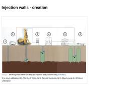
|

(Image: Working steps when creating an injection wall (column row) [FI-Keller]) |
|

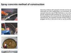
(Image: Application of the spray concrete) (Image: Application of the spray concrete) (Image: View into the starting shaft with spray concrete support - Extension of the exhavation) (Image: View into the starting shaft with spray concrete support - Making of the entry opening) Securing surfaces with sprayed concrete can be carried out as necessary as a thin sealing layer, as a structural, reinforced sprayed concrete coat of little thickness or as a … |
|

|
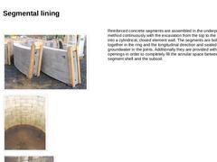
(Image: Segments) (Image: Shaft with view of the unfinished shaft base [FI-Charc]) (Image: Installing a segment in the underpinning method [FI-Charc]) |
Reinforced concrete segments are assembled in the underpinning method continuously with the excavation from the top to the bottom into a cylindrical, closed element wall. The segments are bolted together in the ring and the longitudinal direction and sealed against groundwater in the joints. Additionally … |
|
|

|
|

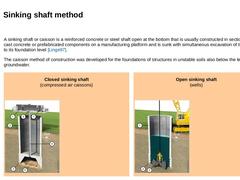
A sinking shaft or caisson is a reinforced concrete or steel shaft open at the bottom that is usually constructed in sections of in-cast concrete or prefabricated components on a manufacturing platform and is sunk with simultaneous excavation of the core to its foundation level [Linge97]. The caisson method of construction was developed for the foundations of structures in unstable soils also below the level of the groundwater. |
|
Closed sinking shaft |
|
|

|
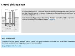
(Image: Closed sinking shaft during building the 26 m deep starting shaft (dimensions 7.5 m x 14 m) for the utility tunnel "Energieversorgungstunnel Kieler Förde" (Bild 9.2.1.3.1) (Bild 9.2.1.3.1) (Bild 2.2.4) [Holzm93b]) |
In closed sinking shafts, a massive pressure retaining cover with the side cutters forms a working chamber open to the bottom through which the water for sinking is forced out by means of compressed air. Air locks and shaft pipes … |
|
|

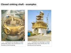
(Image: Creating the exit openings in a closed sinking shaft using in cast concrete [Biele79b] - Recesses of the exit opening) (Image: Creating the exit openings in a closed sinking shaft using in cast concrete [Biele79b] - Bricking up the exit opening) |
|

|
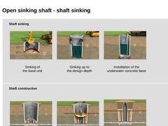
The open sinking shaft is erected on a manufacturer's platform and progressively lowered simultaneously with the excavation and removal of the core from the ground surface to its foundation level. | | | (Image: Attention!)
When sinking into groundwater , the water level inside the shaft must always be maintained at a higher level than outside the shaft in order to prevent a hydraulic soil failure with its attendant damage (cavities outside the shaft, … |
|
|

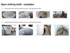
(Table: Sinking shaft made of precast reinforced concrete - Shaft rings) (Table: Sinking shaft made of precast reinforced concrete - Shaft rings) |
|

|
Shaft sinking
|
(Image: Construction phases of the trenchless installation of sewers on the model of microtunnelling - Phase 1 (Sinking of the shaft): Sinking of the base unit of the shaft) |
|
Sinking of
the base unit |
|
|
(Image: Construction phases of the trenchless installation of sewers on the model of microtunnelling - Phase 1 (Sinking of the shaft): Sinking up to the design depth) |
|
Sinking up to
the design depth |
|
|
(Image: Construction phases of … |
|
|
|