|
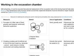
With all jacking, it must be assumed that planned replacement of the excavation tools of the boring head will take place (Abschnitt 9.2.2.1), that maintenance work must be carried out and that unplanned obstacles must be removed or repair measures must be carried out (Tabelle 9.2.2.5.4) [Tunnel01]. (Table: Measures for stabilizing the working face and for reducing the permeability when using compressed air [Girms00] [Girms97b]) There are two possibilities … |
|
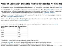
In Germany and Europe, slurry shields are usually used only in the nominal pipe size range of up to DN/ID 1500 [Suhm00]. From DN/ID 1600, the hydroshield is used (up to an external shield diameter of 14.20 m [FI-Herreb] because only from this nominal size, for geometrical reasons, a sufficiently large volume for the compressed air cushion in the pressure chamber can be formed and it has been shown that otherwise the control of the conveying circuit … |
|
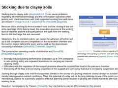
(Image: Possible problems regarding the method technology when jacking in cohesive soils with a high sticking potential with reference to [Sager00] [Image: S&P GmbH]) Sticking due to clayey soils (Abschnitt 8.3.1.2) can cause problems regarding the method technology and the construction operation when jacking with shield machines with fluid supported working face and these are shown in Bild 9.2.2.5.6 [Girms97b] [Thewe99] [Sager00]. Because of the sticking … |
|
According to DIN 18319 [VOBC00c], the decisive criteria when boring in rock are the uniaxial compressive strength and the spacing of discontinuities. The use of slurry shields and hydroshields with rock cutting heads is carried out in rock, without limitation of nominal size, with a uniaxial compressive strength up to a maximum of 300 N/mm2 (classes FD 1/FZ 1 to FZ 4/FD 4 according to DIN 18319 [VOBC00c]) [FI-Herreb]. As regards the tool life times, … |
|
|
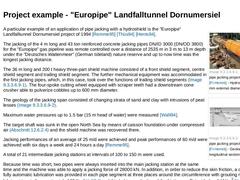
(Image: "Europipe" pipe jacking project (Bild 12.6.2.4) [FI-Herreb] - Hydroshield (3820 mm external diameter))
|
|
(Image: "Europipe" pipe jacking project (Bild 12.6.2.4) [FI-Herreb] - Geological longitudinal section)
|
A particular example of an application of pipe jacking with a hydroshield is the "Europipe" Landfalltunnel Dornumersiel project of 1994 [Remme95] [Thüs94] [Hents94]. The jacking of the 4 m long and 43 ton reinforced concrete jacking … |
|
|
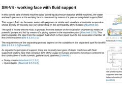
(Image: Diagram of the fluid circuit [FI-Wayss])
|
|
(Image: Spoil conveying with shield machines with fluid supported and earth pressure balanced working face based on [Maidl01b])
|
In this closed type of shield machine (also called liquid pressure balance shield machine), the water and earth pressure at the working face is countered by means of a pressure-regulated support fluid.
This support fluid can be water, water with polymers or similar and …
|
|
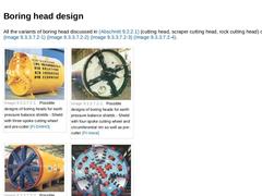
All the variants of boring head discussed in Abschnitt 9.2.2.1 (cutting head, scraper cutting head, rock cutting head) can be used (Bild 9.2.2.6.1) (Bild 9.2.2.6.1) (Bild 9.2.2.6.1) (Bild 9.2.2.6.1). | (Image: Possible designs of boring heads for earth pressure balance shields - Shield with three-spoke cutting wheel and pre-cutter [FI-DAIHO]) | (Image: Possible designs of boring heads for earth pressure balance shields - Shield with four-spoke cutting … |
|
|
It must be expected with every jacking that planned changes of tools and maintenance work needs to be carried out at the boring head and that unplanned obstacles must be removed or repair works must be carried out (Tabelle 9.2.2.5.4) [Tunnel01]. The measures to be taken for these works are discussed in principle in the section on shield machines with fluid supported working face (Abschnitt 9.2.2.5). Special problems for this particular case, however, … |

|
Earth pressure balance shields are generally used for jacking pipes from DN/ID ≥ 1400 and jacking lengths, depending on the jacking pipe nominal size, of between 300 m and 2500 m (Tabelle 9.2.2.6.3). (Table: Guide values for jacking lengths with reference to the nominal size of the jacking pipe for earth pressure balance shields according to the manufacturer's information [FI-Herreb]) The jacking performance depends on the conveying system in use (… |
|
|
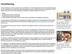
(Image: Possibilities of foam conditioning - Sketch of principle - Injection into the excavation chamber and in front of the boring head with reference to [FI-Herreb] [Image: S&P GmbH]) |
|
(Image: Possibilities of foam conditioning - Sketch of principle - Test run of a shield machine DN/ID 1500 in the works [FI-Herreb]) |
|
(Image: Possibilities of foam conditioning - Sketch of principle - Injection only through the boring head [FI-Kawas]) |
|
(Image: Expanding … |
|
|
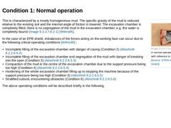
(Image: EPB shield in normal operation (Condition 1) with reference to [Wilms95] [Image: S&P GmbH]) This is characterized by a mostly homogeneous mud. The specific gravity of the mud is reduced relative to the existing soil and the internal angle of friction is lowered. The excavation chamber is completely filled, there is no segregation of the mud in the excavation chamber, e.g. the water is completely bound (Bild 9.2.2.6.5.1) [Wilms95]. In the case … |
|
|
(Image: EPB shield with incomplete filling of the working chamber with danger of caving (Condition 2a) with reference to [Wilms95] [Image: S&P GmbH])
|
|
(Image: EPB shield with hardened material in the upper part of the excavation chamber through bulging and uncontrolled soil removals in the lower part (Condition 2 b) with reference to [Maidl97b] [Image: S&P GmbH])
|
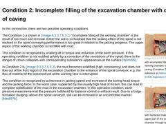
In this connection, there are two possible operating conditions. The Condition 2 a … |
|
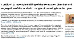
(Image: EPB shield with incomplete filling of the excavation chamber and segregation of the mud with danger of breaking into the open (Condition 3) with reference to [Wilms95] [Image: S&P GmbH]) Condition 3 takes over immediately from Condition 2 a or after longer periods of inactivity (stops). Again, the excavation chamber is incompletely filled with mud, whereby in comparison with Condition 2 a, the upper region of the excavation chamber has filled … |
|
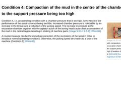
(Image: EPB shield with compaction of the mud in the excavation chamber centre due to the support pressure being too high (Condition 4) with reference to [Wilms95] [Image: S&P GmbH]) Condition 4, i.e. an operating condition with a chamber pressure that is too high, is the result of the performance of the spiral conveyor being too little. Increased chamber pressure is noticeable by an increase in the torque and a reduction of the jacking speed. The … |
|
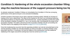
(Image: EPB shield with hardened material in the whole excavation chamber caused by the support pressure being too high (Condition 5) with reference to [Wilms95] [Image: S&P GmbH]) As already mentioned, Condition 5 follows on immediately from Condition 4 if the low conveying performance of the spiral conveyor is not corrected immediately. A further increase in the torque occurs with a reduction of jacking speed, whereby an increase of heating of the … |
|
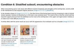
When encountering soil or rock strata with different moduli of elasticity and strengths at the working face, severe problems can arise in the maintenance of the required support pressure (Bild 9.2.2.6.5.6) [Maidl97b]. In the situation shown in Bild 9.2.2.6.5.6, the drive force of the boring head must be increasing in order to loosen the rock stratum (greater modulus of elasticity E2) in the lower cross sectional area. The result of this is that the … |

|
Critical operating conditions of an EPB shield can occur even through small deviations of balance conditions, with excavation chamber overpressure as well as with under-pressure. The causes of this can be operating errors of the shield machine as well as adaptations to changing subsoil conditions not being carried out in time. |
|
Besides the "normal" excavation tool wear (Abschnitt 4.3.5.10) that EPB shields are subject to due to the contact of the excavation tools with soil or rock material at the working face and which can be countered by suitable measures (e.g. tool geometry, choice of materials), there are additional special phenomena of wear [Wilms95] caused by the method technology of earth pressure support. This additional wear is the result of the kneading and agitation … |

|
(Image: Discharging the mud via a belt conveyor [FI-Herreb]) Shield machines with earth pressure supported working face, also called Earth Pressure Shields or EPB (EPB = Earth Pressure Balance) shields, are closed shields in which the earth and water pressures at the working face are balanced with the aid of the soil excavated by the boring head in the pressure-controlled excavation chamber. In order to carry out support effects and pressure balance, … |
|
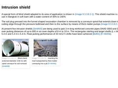
A special form of blind shield adapted to its area of application is shown in Bild 9.2.2.7.1. This shield machine is at present in use in Bangkok in soft loam with a water content of 40% to 140% The soil plug pressed into the funnel shaped excavation chamber is removed by a conveyor spiral that extends down to the lower cutting edge through the pressure bulkhead and then to the surface by means of thick matter pumps (Bild 9.2.2.7.1) [Bell01]. At present … |
|
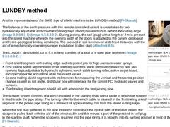
| (Image: LUNDBY method type SLA 1400 for nominal pipe sizes DN/ID 1400 [FI-Skansb] - Front view) | | (Image: LUNDBY method type SLA 1400 for nominal pipe sizes DN/ID 1400 [FI-Skansb] - Longitudinal section) |
Another representative of the SM-B type of shield machine is the LUNDBY method [FI-Skansb]. The balance of the earth pressure with this remote controlled variant is undertaken by two hydraulically adjustable and closable opening flaps (doors) situated … |

|
|

|
Unscheduled changes of method by means of modification are carried out from the pipe string or from a specially excavated auxiliary shaft. Modification is work, cost and time intensive and can take several weeks. Because of the time lost, it may be necessary to carry out methods for speeding up and to take measures for temporary support or balance of the working face by means of soil stabilization. Unscheduled modification should be excluded as far … |

|
An expected or scheduled change of method technology must be taken into account early on in the planning phase. In order to be able to undertake the changes in the shield machine in the starting or an intermediate shaft, the shaft is sunk at the transition point of the changed subsoil conditions. If modification in the shaft is not possible due to topographical or other reasons, then it is carried out in the protection of a specially built station … |

|
In view of the difficulties, costs and time required for a scheduled change of method by means of modification, variable shield types have been developed which permit a change of the method technology to be carried out in a few working shifts, even in a few hours. The change can then take place at any desired jacking position [Tunnel01]. The investment costs for such a shield machine are usually greater as a change of method often also results in … |