|
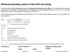
In the case that the drill rod string provides the minimum permissible curve radius, it is to be determined according to the manufacturer’s information. As guide values in this regard the minimum bending radii given in Table 31 can be assumed with reference to the size of the drill rig or the diameter of the drill rod. For drill rod strings by the manufacturer COLLI DRILL [HDD-137], the minimum bending radius Rmin, for example, can be calculated with … |
|
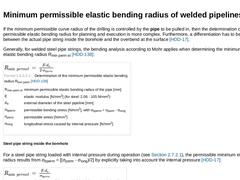
If the minimum permissible curve radius of the drilling is controlled by the pipe to be pulled in, then the determination of the minimum permissible elastic bending radius for planning and execution is more complex. Furthermore, a differentiation has to be made between the actual pipe string inside the borehole and the overbend at the surface [HDD-17]. Generally, for welded steel pipe strings, the bending analysis according to Mohr applies when determining … |
|
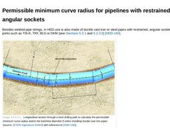
Besides welded pipe strings, in HDD use is also made of ductile cast iron or steel pipes with restrained, angular sockets and spigot joints such as TIS-K, TKF, BLS or DKM (see (Joints of ductile cast iron pipes) and (Restrained plug and socket joints)) [HDD-140]. (Image: Longitudinal section through a bent drilling path to calculate the permissible minimum curve radius and/or the borehole diameter D when installing ductile cast iron pipes) With reference … |
|
The curve radius of the borehole plays a decisive part when it comes to designing the drill profile. The minimum permissible curve radius is either given by the minimum bending radius of the drill rod, the minimum permissible elastic bending radius or the permissible minimum curve radius of the pipe string to be pulled in [HDD-17]. As a rule, the planning of the relevant minimum permissible curve radius for small drilling projects and PE pipes orients … |
|
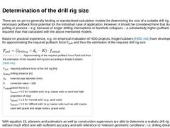
There are as yet no generally binding or standardised calculation models for determining the size of a suitable drill rig, i.e. of the necessary pullback force potential for the individual case of application. However, it should be considered here that during the pulling-in process – e.g. because of longer drilling interruptions or borehole collapses – a substantially higher pullback force may be required than that calculated with the above mentioned … |

|
For several years now, numerous programs, so-called Bore Planning Tools, have been available on the international market. They are intended to simplify the software- based planning and realisation of HDD projects. These software tools (e.g. Atlas Bore Planner™ [HDD-131], Grundo Bore Planner [HDD-23], Phrikolat Bohrlinienplaner [HDD-54], Boretech Holland [HDD-46] [HDD-132]), which are relatively easy to handle and are often offered by the drill manufacturers, … |

|
When calculating the structure of pipes which are to be installed by means of HDD, it is differentiated between calculations for the -
state of construction and the
-
state of operation [HDD-17].
|

|
The calculations for the state of construction do not
only include the structural calculation of the pipeline
to be pulled-in (calculation of the pullback force, static
verification), but also the structural analysis of the
supporting measures that are necessary for the realisation
such as ballasting and abutment. |
|
During the construction state, the maximum pullback force that is to be expected for the pipeline is determined. Here, it is differentiated between -
pullback forces at the pulling head for overcoming the friction forces created in the pipeline, and the
-
pullback forces at the drill head [HDD-17].
The maximum pullback force that is to be expected at the pulling head is decisive for the dimensioning and suitability of the chosen pipe material; the pullback … |
|
Internationally, various methods for calculating the pullback force are available, by means of which the maximum pullback forces that are to be expected at the pulling head inside the pipeline can be calculated or estimated. From experience, the maximum value occurs shortly before completing the pulling-in process, i.e. when nearly the entire pipeline is situated inside the borehole [HDD-17] [HDD-136] [HDD-142]. |
|
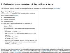
The maximum pullback force at the pulling head can be estimated as follows according to [HDD-136]: A more accurate determination of the pullback forces during pulling-in, for example, is based on calculation methods of the Dutch standard NEN 3651 [HDD-143], of the American Gas Association (AGA) [HDD-148] for steel pipes or the ASTM Active Standard F1962-05 for PE-pipes [HDD-144]. Furthermore, planning offices or institutes … |
|
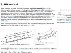
(Image: Longitudinal section (drilling profile) of an HDD project with 5 sections)In the following, the rather frequently used AGA calculation method [HDD-148] for determining the pullback force at the pulling head of steel pipelines will be introduced as an example. The method is used in a metrically converted form [HDD-149]. The maximum pullback force is determined for the entire distance of the horizontal drilling by adding up the pullback forces, … |

|
(Image: Longitudinal section (drilling profile) of a HDD project with 3 sections)This calculation method according to ASTM Active Standard F1962-05 [HDD-144] was originally developed for PE-pipes that are pulled in by drill rigs with a pullback force of > 44.5 kN (> 10,000 lbs). Unlike the above described AGA-method [HDD-148], here the required pullback force is determined by taking into account the friction between pipe and ground surface or roller … |
|
Internationally, various methods for calculating the pullback force are available, by means of which the maximum pullback forces that are to be expected at the pulling head inside the pipeline can be calculated or estimated. From experience, the maximum value occurs shortly before completing the pulling-in process, i.e. when nearly the entire pipeline is situated inside the borehole [HDD-17] [HDD-136] [HDD-142]. |
|
During the construction state, the maximum pullback force that is to be expected for the pipeline is determined. Here, it is differentiated between -
pullback forces at the pulling head for overcoming the friction forces created in the pipeline, and the
-
pullback forces at the drill head [HDD-17].
The maximum pullback force that is to be expected at the pulling head is decisive for the dimensioning and suitability of the chosen pipe material; the pullback … |
|
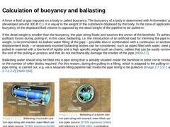
A force a fluid or gas imposes on a body is called buoyancy. The buoyancy of a body is determined with Archimedes’ principle (developed around 300 B.C.). It is equal to the weight of the substance displaced by the body. In the case of application at hand, the buoyancy of the displaced fluid volume is opposed by the dead weight of the pipeline to be pulled-in. If the dead weight is smaller than the buoyancy, the pipe string floats and touches the crown … |
|
The sometimes very high pullback force potential of the drill rigs must be safely absorbed by a suitable abutment if necessary (see (Drill rig)) [HDD-17]. It is recommended to design the abutment to the maximum value of the pullback force of the drill rig to be used [HDD-17]. |
|
The calculated maximum values of the pullback force are used not only for dimensioning the drill rig and the abutment, but also for the stress load of the pipeline. Besides these longitudinal force components, also the stresses resulting from the bending (borehole radius) must be taken into account [HDD-17]. |
|
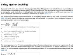
Especially for PE pipes, also evidence of safety against buckling of the pipeline to be pulled in has to be provided considering the pipe bending and external fluid pressure. After consulting the client, the fluid pressure can possibly be compensated for by means of an open pulling head, which allows the drilling fluid to flow into the pipe to be pulled-in, or by filling with water (see (Calculation of buoyancy and ballasting)). In the construction … |

|
The calculations for the state of construction do not
only include the structural calculation of the pipeline
to be pulled-in (calculation of the pullback force, static
verification), but also the structural analysis of the
supporting measures that are necessary for the realisation
such as ballasting and abutment. |

|
The pipelines installed by using HDD have to be calculated for the different kinds of impacts during later operation. |
|
In the calculation of the maximum pipe stresses in the operating condition, one of the most important parameters to be considered is again the stress resulting from bending (borehole curvature). In place of the pullback force which is no longer applied, there is now the stress resulting from internal pressure (see (Minimum permissible elastic bending radius of welded pipelines)) [HDD-17]. |

|
The assessment of safety against buckling is only necessary for flexible pipes, i.e. pipes whose deformation decisively influences the load bearing performance. Contrary to the construction state (see (Safety against buckling)) – the long-term E-modulus (see (PE-pipes)) must be used for the assessment of the safety against buckling during the operating phase of the pipeline [HDD-17]. |

|
Occasionally, it is necessary to assess the expected life time of the pipeline within the respective framework of borehole conditions. This is of use especially in strongly corrosive environments (external corrosion), for very high temperatures and aggressiveness of the transported medium (internal corrosion) [HDD-17]. |
|
(Image: Bedding of an HDPE gas pipe installed by HDD – Schematic details of the pipe bedding)The bedding of pipes installed by HDD is of particular importance (Figure 119a, b and c), because they are a fundamental component of the load bearing system. Among others, Gaile [HDD-160] and Behrendt [HDD-161] [HDD-162] as well as Knight [HDD-145] report of investigations in this regard. In the course of time, the bentonite suspension hardens due to its … |