|

(Video: Integrated high-pressure flushing system in the crusher space of the AVN microtunnelling machine) |
|

|
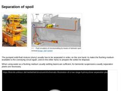
(Image: Separation of the spoil by a separation plant (compact plant MAB 300 with a solids capacity of 75 t/h) [FI-Schau]) (Image: Fluid circulation of microtunnelling by means of hydraulic spoil removal)
The pumped solid-fluid mixture (slurry) usually has to be separated in order, on the one hand, to make the flushing medium available to the conveying circuit again, and on the other hand, to prepare the solids for disposal.
When using water as … |
|
|

|
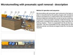
(Image: Microtunnelling with pneumatic spoil removal)
|
|
(Image: Equipment, possible arrangement of the components on the construction site and space requirements (approximately L x W = 34 x 4 m) in microtunnelling with pneumatic spoil removal - plan view (on the model of the jacking of pipes DN/ID 600, pipe length 2.0 m))
|
|
Method of operation and sequence Microtunnelling with pneumatic spoil removal on the basis of a suction plant is characterized … |
|
|

|
|

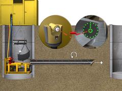
This lecture is part of the series "Trenchless 101" and serves to provide an overview of steerable trenchless new installation methods for gas, water and wastewater pipelines. |
|

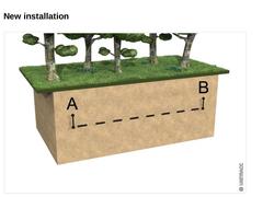
Today, supply and discharge lines are still predominantly installed by using the open-cut method: a trench is dug, the lines are installed. Under the protection of an embankment or sheeting and the trench is filled afterwards. In the face of the numerous disadvantages as well as the citizens' growing environmental consciousness in the future it is urgently necessary to take trenchless technology into account much stronger than until today as an alternative … |
|

| (Image: New installation)
|
|
|

|
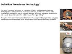
The term "Trenchless Technology for Installation of Cables and Pipelines by Jacking or Drilling" (referred to hereareafter as trenchless installation), is understood to mean "The Underground installation of lines by means of pulling in, pushing in, pressing in or ramming in into a cavity (borehole) made in the soil by means of boring or drilling." Today, the methods of trenchless installation allow the underground laying of cables and pipes irrespective … |
|
|

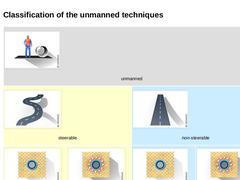
| (Image: Unmanned techniques)
unmanned | | (Image: Steerable techniques)
steerable | (Image: Non-steerable techniques)
non-steerable | | (Image: Soil removal techniques)
soil removal | (Image: Soil displacement techniques)
soil displacement | (Image: Soil removal techniques)
soil removal | (Image: Soil displacement techniques)
soil displacement |
|
|

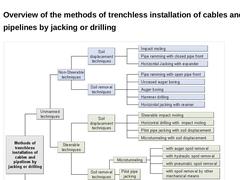
| (Image: Overview of the methods of trenchless installation of cables and pipelines by jacking or drilling)
|
|

|

|
|

|
(Image: Unmanned techniques)
|
|
(Image: Steerable techniques)
|
|
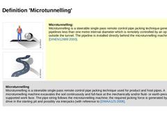
Microtunnelling:
Microtunnelling is a steerable single pass remote control pipe jacking technique generally for pipelines less than one metre internal diameter which is remotely controlled by an operator from outside the tunnel. The pipeline is installed directly behind the microtunnelling machine [DINEN12889:2000]. | |
Microtunnelling
Microtunnelling is a steerable single pass remote control … |
|
|

|
(Image: Unmanned techniques)
|
|
(Image: Steerable techniques)
|
|
(Image: Soil removal techniques)
|
|
(Image: Soil displacement techniques)
|
|
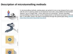
In microtunnelling methods, jacking pipes are jacked (in one or two phases) from a starting shaft with the aid of a jacking station (in exceptional cases also using additional intermediate jacking stations ) up to a target shaft . At the same time an unmanned , remote controlled microtunnelling machine carries … |
|
|

|
(Image: Soil removal techniques)
|
|
(Image: Microtunnelling with auger spoil removal)
|
|
(Image: Microtunnelling with hydraulic spoil removal)
|
|
(Image: Microtunnelling with pneumatic spoil removal)
|
|
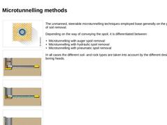
The unmanned, steerable microtunnelling techniques employed base generally on the principle of soil removal. Depending on the way of conveying the spoil, it is differentiated between: - Microtunnelling with auger spoil removal
- Microtunnelling with hydraulic …
|
|
|

|
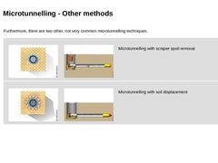
Furthermore, there are two other, not very common microtunnelling techniques. | |
(Image: Soil removal techniques)
|
(Image: Microtunnelling with spoil removal by other mechanical means (spoil removal by a scraper arrangement))
|
Microtunnelling with scraper spoil removal | |
(Image: Soil displacement techniques)
|
(Image: Microtunnelling with soil displacement)
|
Microtunnelling with soil displacement |
|

|

|
|

|
(Image: Technical components in microtunnelling)
|
|
(Image: Equipment, possible arrangement of the technical components on the construction site and space requirement in microtunnelling with auger spoil removal - top view)
|
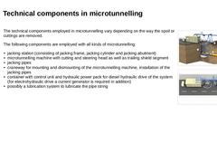
The technical components employed in microtunnelling vary depending on the way the spoil or cuttings are removed. The following components are employed with all kinds of microtunnelling: - jacking station (consisting of jacking frame, …
|
|

|

|
|

|
(Image: Technical components for microtunnelling with auger spoil removal in single phase jacking)
|
|
(Image: Equipment, possible arrangement of the components on the construction site and space requirement (approximately L × W = 22.0 × 4.0 m) in microtunnelling with auger spoil removal - top view (on the model of the jacking of pipes DN/ID 600, pipe length 2.0 m))
|
|
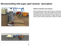
Method of operation and sequence Microtunnelling with auger spoil removal is characterized … |
|
|

The spoil loosened at the working face with the aid of the cutting head is transported to the starting shaft by the spiral conveyor and is there collected in a spoil bucket. Using lifting tackle, this is lifted to the surface when full at determined intervals, usually after jacking a pipe piece. The pressure at the working face is mechanically balanced by the cutting head or by means of the soil plug that is formed in the front section of the conveyor … |
|

|
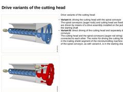
(Image: Microtunnelling with auger spoil removal in single phase jacking - Variant: driving the cutting head with the spiral conveyor)
|
|
(Image: Microtunnelling with auger spoil removal in single phase jacking - Variant: direct driving of the cutting head and separately driven spiral conveyor)
|
Drive variants of the cutting head: - Variant A: driving the cutting head with the spiral conveyor
The spiral conveyors (auger rods) and cutting head are fixed …
|
|

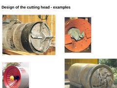
| (Image: Example of cutting head driven with the spiral conveyor [Becke96])
| (Image: Example of cutting head driven with the spiral conveyor [FI-Herreb])
| | (Image: Example of cutting head driven with the spiral conveyor [FI-Wirthb])
| (Image: Example of cutting head driven with the spiral conveyor [FI-Schrö])
|
|

|

| (Image: Pros and cons)
(Table: Advantages and disadvantages of microtunnelling with auger spoil removal) |
|
|

|
|

|
(Image: Microtunnelling with hydraulic spoil removal in single phase jacking)
|
|
(Image: Basic equipment, possible arrangement components on the construction site and space requirements (ca. L × B = 35 × 4 m) for microtunnelling with hydraulic spoil removal - plan view (on the model of the jacking of pipes DN/ID 600, pipe length 2.0 m))
|
|
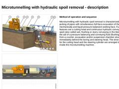
Method of operation and sequence Microtunnelling with hydraulic spoil removal is characterized by the jacking … |
|