
|
With jacking in cohesive soils, it must be assumed that the overcut closes again due to consolidation and creep processes in the soil so that, in the calculation of the pipe loading, it must not be taken into account. The determination of the load perpendicular to the pipe axis is carried out in this case analogous to Abschnitt 14.6.1.1. The external radius of the pipe must be used for the dimensions of the void expansion, e.g. of the soil displacement. |

|
(Image: Formation of the fracture bodies in the soil for soil displacement methods with overcut in non-cohesive soils [Falk97b]) The load assumptions to ATV-A 161E [ATVA161] apply in this case. With flexible pipes or pipe materials such as plastics or steel, an increase of the bedding reaction pressure resulting from the compaction of the soil in the immediate vicinity of the pipe with the result of an increase in the soil strength can be assumed. … |
|
|
|
Because of the overcut, the traversed cavity is, in many cases, stable in the construction condition so that the pulled, pushed or pressed in pipe is not subject to loading at the start. This temporary stability is improved in the soil displacement method in comparison to the soil removal method by means of: - The compaction of the soil in the vicinity of the pipe and the thus resulting soil properties
- The stress condition created by the expansion
- The …
|
|
|
|
|
|
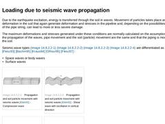
Due to the earthquake excitation, energy is transferred through the soil in waves. Movement of particles takes place and thus deformation in the soil that again generate deformation and stresses in the pipeline and, depending on the possibilities of movement of the pipe string, can lead to more or less severe damage. The maximum deformations and stresses generated under these conditions are normally calculated on the assumption that during the propagation … |
|
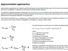
Approximation approaches are methods used for estimating the permissible limiting values of the strains and curvatures. Their accuracy is acceptable in comparison to the dynamic and quasi-static methods. The following simplified calculation method given in [Wang80] [Newma67] is based on the assumption that the seismic wave patterns do not alter and that the pipe and soil movements are the same size. Pipe strains and curvatures occur as well as relative … |
|
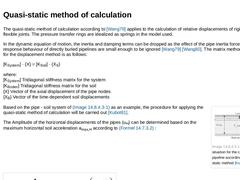
The quasi-static method of calculation according to [Wang79] applies to the calculation of relative displacements of rigid pipes with flexible joints. The pressure transfer rings are idealized as springs in the model used. In the dynamic equation of motion, the inertia and damping terms can be dropped as the effect of the pipe inertia forces on the response behaviour of directly buried pipelines are small enough to be ignored [Wang79] [Wang80]. The … |
|
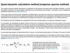
The response spectra method represents a combination of the dynamic and quasi-static calculation methods. It can be used when the pipeline, because of its great rigidity is idealized as a bar framework and the pipe - soil system can be modelled by springs and substitution dimensions [Kraus84] [Flesc97]. In this case, based on the dynamic calculation soil deformations, the pipe cross sections are quasi-statically determined. Here it is assumed that … |
|
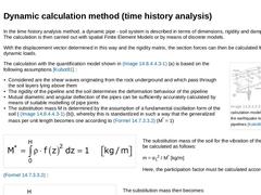
In the time history analysis method, a dynamic pipe - soil system is described in terms of dimensions, rigidity and damping matrixes. The calculation is then carried out with spatial Finite Element Models or by means of discrete models. With the displacement vector determined in this way and the rigidity matrix, the section forces can then be calculated from the dynamic loads. (Image: Dynamic calculation model for determining the earthquake loading … |
|
|
|
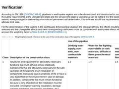
According to EN 1998 [DINENV1998-4], pipelines in earthquake regions are to be dimensioned and constructed in such a way that the safety requirements at the ultimate limit state and the service limit state of usefulness can be fulfilled. For the types of effects of seismic wave propagation and earthquake-induced permanent soil deformation, it is sufficient to fulfil the requirements at the ultimate limit state. For the determination of the loading … |

|
In the planning of pipeline or pipeline systems, regions with a high potential of earthquake damage should be circumnavigated as far as possible. This includes regions, for instance: - In or above saturated, sandy or silty soils
- Toes of slopes
- With active distortions (large displacements)
- With large changes of the relevant dynamic soil properties
- With strong morphological and geological discontinuities
If these regions cannot be circumnavigated, then … |
|
|
|
|
|
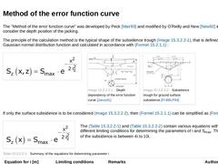
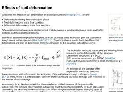
The "Method of the error function curve" was developed by Peck [Mair93] and modified by O'Reilly and New [New92] in order to also consider the depth position of the jacking. The principle of the calculation method is the typical shape of the subsidence trough (Bild 15.2.1.1), that is defined by the Gaussian normal distribution function and calculated in accordance with Formel 15.2.1.1 : (Formula: Error Function Curve)
|
(Image: Depth dependency of the … |
|
|
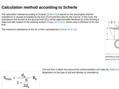
(Image: Depth dependency of the error function curve [Scher77c]) The calculation method according to Scherle [Scher77c] is based on the assumption that the subsidence is caused principally by the loss of soil and thus also by the overcut. In this case, the subsidence line formed at the ground level (GL) will be approximately idealized by a line forming a trapezoid with respect to the existing surface (Bild 15.2.1.2) whose area is identical to the … |
|
|
|
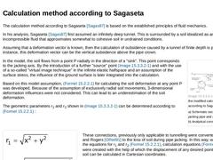
The calculation method according to Sagaseta [Sagas87] is based on the established principles of fluid mechanics. In his analysis, Sagaseta [Sagas87] first assumed an infinitely deep tunnel. This is surrounded by a soil idealized as an incompressible fluid that approximates somewhat to cohesive soil in undrained conditions. Assuming that a deformation vector is known, then the calculation of subsidence caused by a tunnel of finite depth is possible. … |
|
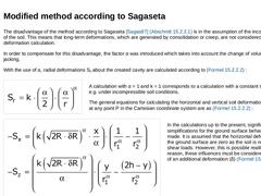
The disadvantage of the method according to Sagaseta [Sagas87] (Abschnitt 15.2.2.1) is in the assumption of the incompressibility of the soil. This means that long-term deformations, which are generated by consolidation or creep, are not considered in the deformation calculation. In order to compensate for this disadvantage, the factor α was introduced which takes into account the change of volume during pipe jacking. With the use of α, radial deformations … |

|
|
|
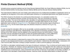
Included among numerical methods are the Finite Element Method (FEM), the Finite Difference Method (FDM), the Kinematic Element Method (KEM), the Boundary Element Method (BEM) and the Discrete Element Method (DEM). The Finite Element Method is the most widely used method due to its multifaceted possibilities of application and its particular suitability for the depiction of the stress and deformation behaviour of complicated geometries and spatial … |
|
|
|
(Image: Effects of soil deformation on adjoining structures [Attew86]) Critical for the effects of soil deformation on existing structures (Bild 15.3) are the - Deformations during the construction phase
- Total deformations in the final condition
- Differential deformations in the final condition
Differential deformations cause displacement or deformation at existing structures, pipes and traffic surfaces and thus additional loading. In order to estimate … |