|
Even though pipe bursting using the hydraulic bursting method is still utilised internationally, its use in the German market is negligible. The main reason for this is the development of the static pipe bursting, which does not require additional pit excavation but rather uses existing manhole structures in conjunction with accordingly dimensioned discrete pipes to deliver a much faster, continuous (single-phase), bursting process as opposed to that … |
|
|
|
For the quality assurance purposes, all of the equipment used for the pulling in of the new pipeline is to be used in accordance with the manufacturer’s recommendations and within the limits of the expected forces. In addition, the contractor must document all relevant working steps, whereby the exact type and scope of the documentation must be defined between the owner and the contractor prior to the commencement of work. The … |
|
On-site Documentation According to [DWAM143-15:2005] the on-site documentation should at least include the following documents: -
Bursting protocol
-
Daily site report
-
Material reception inspection
-
Welding protocol according to [DVSM2207] (if required)
-
Protocol of the tensile forces during the pulling-in, or rather documentation of the overload protection (if used)
-
Protocols of the leaktightness testing as per [DINEN1610:1997] (…
|

|
(Image: Leaktightness) Finishing work and Quality Testing In order to ensure that the sewers and pipelines replaced using pipe bursting maintain the same durability and performance as those replaced using the open cut method, the same finishing work and quality tests according to DIN EN 1610 also apply [DWAM143-15:2005]. Tests: -
Visual inspection
-
Leaktightness testing
-
Testing the deformation of flexible pipes, if required
|

|
Contractor Qualification Subject to EU-guideline from 17/09/1990 (Annex. C of DIN EN 1610), the client can make use of a reference system to check the qualifications of key suppliers or companies. In Germany the Güteschutz Kanalbau eV represents such a system. |
|
|
|
Replacement refers to the installation of sewers and drains in place of existing pipelines, where the new pipeline takes over the functions of the old system. The focus of this module is the trenchless replacement method by the means of pipe bursting. In addition to the process description, the areas of application and limits as well as options for quality assurance are discussed. Upon the successful completion of this module, you will be able to: - identify and implement the most important rules and specifications,
- select the appropriate replacement methods based on the type of damage and limiting conditions, and
- identify possible causes of errors and describe quality assurance measures.
|
|
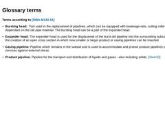
Terms according to [DWA-M143-15] -
Bursting head: Tool used in the replacement of pipelines, which can be equipped with breakage-rails, cutting rollers or similar - dependant on the old pipe material. The bursting head can be a part of the expander head.
-
Expander head: The expander head is used for the displacemet of the burst old pipeline into the surrounding subsoil, and also for the creation of an open cross section in which new smaller or larger …
|
|
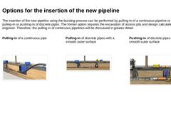
The insertion of the new pipeline using the bursting process can be performed by pulling-in of a continuous pipeline or through the pulling-in or pushing-in of discrete pipes. The former option requires the excavation of access pits and design calculations from an engineer. Therefore, the pulling-in of continuous pipelines will be discussed in greater detail. Pulling-in of a continuous pipe Pulling-in of discrete pipes with a smooth outer surface |
|
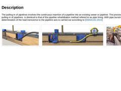
The pulling-in of pipelines involves the continuous insertion of a pipeline into an existing sewer or pipeline. The process for the pulling-in of pipelines is identical to that of the pipeline rehabilitation method refered to as pipe lining. With pipe bursting however a determination of the load transverse to the pipeline axis is carried out according to [DWAA161:2010] (Image: Illustration of the pneumatic pipe bursting - pulling-in of a continuous … |
|
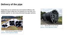
Depending on its nominal size and material stiffness, the pipeline is either rolled up in its entirety on a coil reel, or is welded together on site using individual long pipe sections. (Image: HD-PE discrete long pipes DA 500) (Image: HD-PE-pipe on a as coil reel) |
|
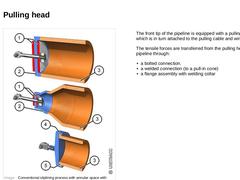
(Image: Conventional sliplining process with annular space with reference to [FI-Teerb] [Image: S&P GmbH] - Design of pulling heads for pipes DN 140 to DN 1200) The front tip of the pipeline is equipped with a pulling head which is in turn attached to the pulling cable and winch. The tensile forces are transferred from the pulling head to the pipeline through: -
a bolted connection.
-
a welded connection (to a pull-in cone)
-
a flange assembly with welding …
|
|
Monitoring temperature variations when working with plastic pipes is of essential importance as they can lead to changes in length of the pipeline which can cause problems, particularly on hot summer days. To avoid this problem, the pipeline insertion should take place in the early mornings when the material temperature and the air temperature in the old pipeline are almost the same. |
|
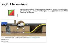
Depending on the depth of the old sewer or pipeline, the construction of relatively long insertion pits is necessary in order to prevent damage to the new pipeline as a result of the formation of very small bending radii.
(Image: Static pipe bursting - Pulling-in of the new pipeline) |
|
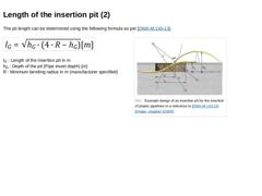
The pit length can be determined using the following formula as per [DWA-M 143-13]: (Formula: Die Baugrubeläange) lG : Length of the insertion pit in m
hG : Depth of the pit (Pipe invert depth) [m]
R : Minimum bending radius in m (manufacturer specified)
(Image: Example design of an insertion pit for the insertion of plastic pipelines in a reference to [DWA-M143-13])
|
|
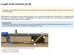
The length of the insertion pit is determined by several factors, the most relevant being the minimum radius of curvature RK [m] of the new pipeline. Plastic pipelines are distorted during the bending process in such a way that the outside bend of the pipeline (1) is elongated and the inside bend in compressed (2). Therefore, the strain limits of the pipeline must be taken into account during the insertion process, and a distortion or stress analysis … |
|
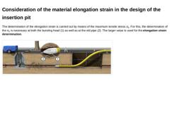
The determination of the elongation strain is carried out by means of the maximum tensile stress σz. For this, the determination of the σz is necessary at both the bursting head (1) as well as at the old pipe (2). The larger value is used for the elongation strain determination. (Image: Static pipe bursting - Pulling-in of the new pipeline)
|
|
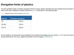
The DVS guideline 2205-1 specifies elongation limits for various plastic materials free from residual stress (isotropic material). The limits for the safe installation conditions (short-term, γ = 1.4) are given in the following table. (Table: Elongation limits of various plastics [DVSM2205]) For PE pipelines, the total outer bend elongation (from pulling and bending) may not exceed ε = 3 %. Due to the risk of buckling during compression, the max εK… |
|
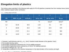
The limiting values specified in the following table apply for PE-HD pipelines (materials free from residual stress (isotropic material)). Other materials require further verification. (Table: Limiting values for PE-HD) 1. Diameter / wall thickness ratio (dL,a, dL,i [mm] Outside-/Inside diameter of the pipeline / liner). 2. Permissible bending radius. 3. Permissible compression reduced by for 3 % for stability purposes. 4. Permissible longitudinal tension … |
|
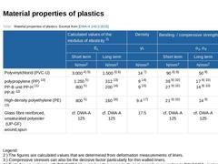
(Table: Material properties of plastics (excerpt from DWA-A 143-2)) Legend: 2 ) The figures are calculated values that are determined from deformation measurements of liners. 3 ) Compressive stresses can also be the decisive factor particularly for thin walled liners. 4 ) Tested in accordance with DIN 54852 (4- point bending creep test) , test procedure according to DIN 53457 , test specimen manufactured according to DIN 16776-2 5 ) Higher values … |
|
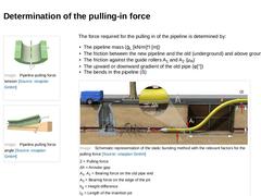
(Image: Pipeline pulling force tension) (Image: Pipeline pulling force angle) The force required for the pulling in of the pipeline is determined by: -
The pipeline mass (ḡL [kN/m]*l [m])
-
The friction between the new pipeline and the old (underground) and above ground (μG)
-
The friction against the guide rollers A1 and A2 (μR)
-
The upward or downward gradient of the old pipe (φ[°])
-
The bends in the pipeline (ß)
(Image: Static pipe bursting pulling … |
|
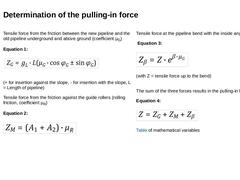
Tensile force from the friction between the new pipeline and the old pipeline underground and above ground (coefficient μG) Equation 1: (Formula: Zugkraft aus Reibung des Rohrstranges im Altrohr Untergrund und auf dem Gelände)
(+ for insertion against the slope, - for insertion with the slope, L = Length of pipeline)
Tensile force from the friction against the guide rollers (rolling friction, coefficient μR) Equation 2: (Formula: Zugkraft aus Reibung … |
|
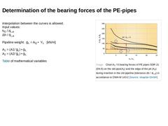
Interpolation between the curves is allowed.
Input values:
hG / dL,a
Δh / dL,a Pipeline weight: ḡL = AQ • YL [kN/m] A1 = (A1/ ḡL) • ḡL
A2 = (A2/ ḡL) • ḡL (→ Table: Equation variables) of mathematical variables (Image: Chart A1 / 6 bearing forces of PE pipes SDR 21 (SN 8) on the old pipe(A1) and the edge of the pit (A2)) |
|
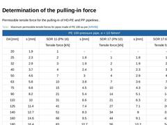
Permissible tensile force for the pulling-in of HD-PE and PP pipelines .
(Table: Maximum permissible tensile forces for pipes made of PE 100) (Table: Maximum permissible tensile forces for pipes made of PE 80) |