
|
|
|
This module focuses on the fundamentals of the trenchless replacement of gas, water, wastewater pipelines using the gallery techniques known from the mining industry. In addition, the individual steps of the gallery heading process with steel and timber support are described - from the preparatory measures to the final work. In addition, the areas of application and limitations of gallery heading, the measures for quality assurance as well as the advantages and disadvantages of this method are presented. After completing this module, you will have a sound knowledge of: - characteristics of gallery heading;
- working steps of this form of heading;
- relevant aspects for quality assurance.
|
|

This lesson focuses on the trenchless replacement of pipelines using the pipe extraction method. The aim is to provide a quick introduction to the subject with regard to process variations and operating limits and limits, as well as to convey the advantages and disadvantages of this replacement process. |
|

|
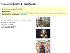
Definition according to DIN EN 752
Replacement:
Construction of a new drain or sewer, on or off the line of an existing drain or sewer, the function of the new drain or sewer incorporating that of the old one. [EN752:2008]. |
|
The replacement is always carried out at least in section lengths of the sewer using: -
The open cut method ;
-
The semi open cut method ;
-
The trenchless method .
|
|
(Image: Replacement of sewers using the open cut method) |
|
(… |
|
|
|

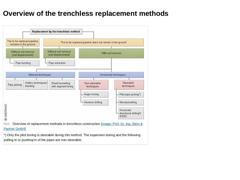
(Image: Overview of replacement methods in trenchless construction) |
|

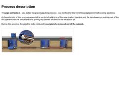
The pipe extraction - also called the pushing/pulling process - is a method for the trenchless replacement of existing pipelines. A characteristic of this process group is the sectional pulling-in of the new product pipeline and the simultaneous pushing-out of the old pipeline with the aid of hydraulic pulling-equipment situated in the reception pit. During this process, the pipeline to be replaced is completely removed out of the subsoil. (Image: Pushing-… |

|

|

|

DIN EN 12889 Pipe Extraction
The original pipeline is extracted by pulling or pushing and simultaneously replaced by a new one. When the diameter of the new pipe is significantly larger than the old, an expander is used [DINEN12889:2000]. |

|

|
|

European Standards: DIN EN 752-5: Drain and sewer systems outside buildings (04.2008) DIN EN 12889: Trenchless construction and testing of drains and sewers (03.2000) |

|

|
|

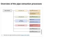
(Image: Overview over pipe extraction processes) |

|

Preparatory work contains: | | (Image: Question)
| (Image: Question)
| (Image: Question)
|
|
|

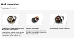
Preparatory work contains: (Image: Inspection) Acquisition of the actual condition of the pipeline to be replaced (pipe diameter, material, depth of cover, directional changes, branches and connections, fittings, clamps, etc.) (Image: Laterals) Removal of obstacles (change of nominal size, directional changes, branches and connections, fittings, clamps, etc.) (Image: Planning) Acquisition of the line's geometry |
|

|
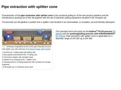
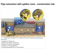
Characteristic of the pipe extraction with splitter cone is the sectional pulling-in of the new product pipeline and the simultaneous pushing-out of the old pipeline with the aid of hydraulic pulling-equipment situated in the reception pit. The pressed out old pipeline is pulled over a splitter cone located in an intermediate, or reception, pit and thereby destroyed. (Image: Schematic longitudinal section of the pipe extraction process with splitter … |
|
|

(Image: Pipe extraction with splitter cone - Replacement of cast iron pipelines [FI-Weiss]) |
|

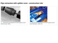
(Image: Pipe extraction for the replacement of cast iron pipelines (Hydros System) [FI-Klug] - Adapter) (Image: Pipe extraction for the replacement of cast iron pipelines (Hydros System) [ATVA127a] - Splitter cone) |
|

|
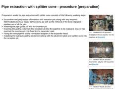
Preparation works for pipe extraction with splitter cone consists of the following working steps: -
Excavation and preparation of insertion and reception pits along with any required intermediate pits near house connections, as well as the removal of the to be replaced pipeline out of all the pits.
-
Installing the pipe guide rail into the insertion pit.
-
Inserting the pulling rods from the reception pit into the pipeline to be replaced. Once it has …
|
|
|

|
(Image: Attention!)
If the pipeline sections to be replaced are significantly long, the installation of intermediate pits for the pipe extraction is possible and due to the skin friction quite reasonable. |
|
Intermediate pits are installed: -
in the vicinity of connection pipelines (service pipelines as well as drains and sewers),
-
in order to subdivide the complete pulling section into shorter, technically controllable sections (about 10 to 15 m).
|
|
|

If an intermediate pit is installed, a splitter cone and a container for pipe fragments are integrated. The discrete pipe sections are continually pulled by the pulling-equipment in the reception pit over the splitter cone, placed in the particular intermediate pit, and destroyed one after the other. (Image: Hydros®-PLUS process - Splitter cone in the intermediate pit [FI-Weiss]) (Image: Hydros®-PLUS process - Destroyed pipeline (grey cast iron pipe … |
|

|
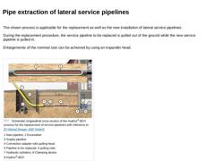
The shown process is applicable for the replacement as well as the new installation of lateral service pipelines.
During the replacement procedure, the service pipeline to be replaced is pulled out of the ground while the new service pipeline is pulled in.
Enlargements of the nominal size can be achieved by using an expander head. (Image: Schematic longitudinal cross section of the Hydros®-BOY process for the replacement of service pipelines with … |
|
|

|
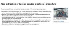
(Image: Hydros®-BOY process - Pulling-equipment positioned in the basement [FI-Weiss])
The procedure for pipe extraction of laterals consists of the following working steps: -
Installing of an insertion pit near the supply pipeline. The installation of a pit within the range of the house connection, or the intermediate pit, may be necessary.
-
Placing of the pulling-equipment based on site requirements in either the basement of the house to be connected, …
|
|
|

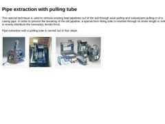
This special technique is used to remove existing lead pipelines out of the soil through axial pulling and subsequent pulling-in of a casing pipe. In order to prevent the breaking of the old pipeline, a special form-fitting tube is inserted through its entire length in order to evenly distribute the necessary tensile force. Pipe extraction with a pulling tube is carried out in four steps. (Image: Hydros®-LEAD process for the replacement of service … |
|

|
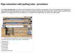
In the first working step, an insertion pit is installed in the area of the main pipeline. The service pipeline to be replaced is separated from the main pipeline as well as from the building. Starting from the insertion pit, a winch cable is pulled into the pipeline to be replaced up to the reception pit, or the basement, respectively, by means of a cable guide. (Image: Pipe extraction with pulling tube - Hydros®-LEAD process with reference to [… |
|
|

|
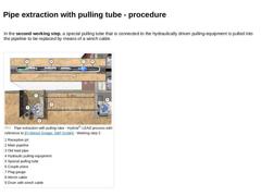
In the second working step, a special pulling tube that is connected to the hydraulically driven pulling-equipment is pulled into the pipeline to be replaced by means of a winch cable. (Image: Pipe extraction with pulling tube - Hydros®-LEAD process with reference to [FI-Weiss] [Image: S&P GmbH] - Working step 2) |
|