|
|
(Image: Construction site) |
The preparatory work comprises the following steps: -
Construction site arrangement (including traffic control / traffic direction)
-
Excavation of the starting pit. A target pit is not necessary in gallery heading
-
Setting of measuring points for the geotechnical measurements before and during the jacking process (quality assurance)
-
Groundwater lowering (if groundwater is existent)
|
|
|
|
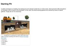
In gallery techniques or heading, the starting pit can be placed outside the run of the sewer, which prevents traffic disruptions. An example of this is shown in the illustration. In this case, the actual working galleries are reached by means of lateral galleries. Target pits are not necessary. (Image: Arrangement of a starting pit on a green traffic island using gallery techniques (heading) with reference to [Scher77b] [Image: S&P GmbH]) |
|

|
|
|
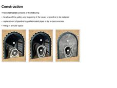
The construction consists of the following: |
(Image: Working steps of gallery techniques (heading) - Exposion of the sewer or pipeline to be replaced) |
(Image: Working steps of gallery techniques (heading) - Installation of the new sewer or pipeline) |
(Image: Working steps of … |
|
|
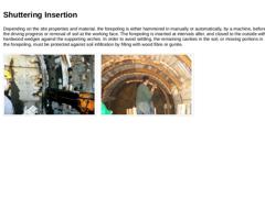
Depending on the site properties and material, the forepoling is either hammered in manually or automatically, by a machine, before the driving progress or removal of soil at the working face. The forepoling is inserted at intervals after, and closed to the outside with hardwood wedges against the supporting arches. In order to avoid settling, the remaining cavities in the soil, or missing portions in the forepoling, must be protected against soil … |
|
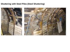
(Image: Gallery technique (heading) with steel shuttering) (Image: Gallery technique (heading) with steel shuttering) |
|
|
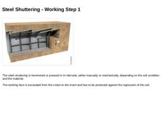
(Image: Working steps for gallery techniques (heading) with steel shuttering) |
The steel shuttering is hammered or pressed in in intervals, either manually or mechanically, depending on the soil condition and the material. The working face is excavated from the crown to the invert and has to be protected against the ingression of the soil. |
|
|
|
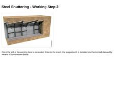
(Image: Working steps for gallery thechnique (haeding) with steel shuttering) |
|
Once the soil of the working face is excavated down to the invert, the support arch is installed and horizontally braced by means of compressive brace. |
|
|
|
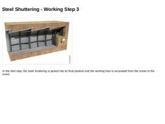
(Image: Working steps for gallery techniques (heading) with steel shuttering) |
|
In the next step, the steel shuttering is jacked into its final position and the working face is excavated from the crown to the invert. |
|
|
|
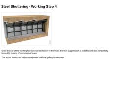
(Image: Working steps for gallery techniques (heading) with steel shuttering) |
|
Once the soil of the working face is excavated down to the invert, the next support arch is installed and also horizontally braced by means of compressive brace.
The above mentioned steps are repeated until the gallery is completed. |
|
|
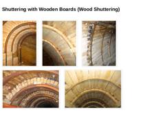
(Image: Gallery technique (heading) with wood shuttering and stable working face (S&P)) (Image: Gallery techniques (heading) with wood shuttering - wood shuttering wedged against support arches) (Image: Gallery techniques (heading) with wood shuttering) (Image: Gallery techniques (heading) with wood shuttering - wood shuttering wedged against support arches) (Image: Gallery techniques (heading) with wood shuttering - wood shuttering wedged against … |
|
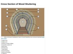
(Image: Gallery techniques (heading) by means of wood forepoling (cross-sectional drawing)) |
|
|
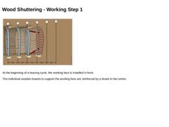
(Image: Working steps for gallery techniques (heading) (sewer to be replaced not shown)) |
|
At the beginning of a bracing cycle, the working face is installed in front. The individual wooden boards to support the working face are reinforced by a board in the centre. |
|
|
|
(Image: Working steps for gallery techniques (heading) (sewer to be replaced not shown)) |
|
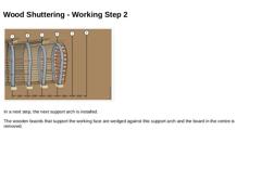
In a next step, the next support arch is installed. The wooden boards that support the working face are wedged against this support arch and the board in the centre is removed. |
|
|
|
(Image: Working steps for gallery techniques (heading) (sewer to be replaced not shown)) |
|
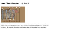
Now the wood shuttering is jacked while the soil is successively excavated in the range of the working face. The working face is secured by individual wooden boards, which are wedged against the support arch. |
|
|
|
(Image: Working steps for gallery techniques (heading) (sewer to be replaced not shown)) |
|
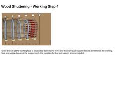
Once the soil at the working face is excavated down to the invert and the individual wooden boards to reinforce the working face are wedged against the support arch, the bedplate for the next support arch is installed. |
|
|
|
(Image: Working steps for gallery techniques (heading) (sewer to be replaced not shown)) |
|
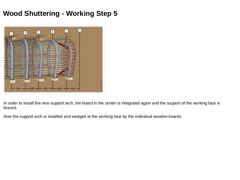
In order to install the new support arch, the board in the center is integrated again and the support of the working face is braced. Now the support arch is installed and wedged at the working face by the individual wooden boards. |
|
|
|
(Image: Working steps for gallery techniques (heading) (sewer to be replaced not shown)) |
|
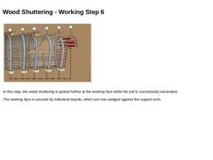
In this step, the wood shuttering is jacked further at the working face while the soil is successively excavated. The working face is secured by individual boards, which are now wedged against the support arch. |
|
|
|
(Image: Working steps for gallery techniques (heading) (sewer to be replaced not shown)) |
|
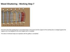
Once the soil of the working face is excavated down to the invert and the support of the working face is wedged against the support arch, the bedplate for the next support arch is installed.
The above mentioned steps are repeated until the gallery is completed. |
|

|
Animation: Gallery technique - Wood shuttering [Image: S&P GmbH]. This interactive object is only visible in the online version of the module. |
|
|
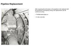
(Image: Gallery techniques (heading) sewer to be replaced has been exposed) [Scher78]) |
After exposing the old sewer or the pipeline to be replaced with the protection of temporary lining, the replacement can be carried out using: -
Prefabricated pipes or
-
In-situ concrete.
|
|

|
There are two available options for replacement with prefabricated pipes: -
Option 1: laying the temporary by-pass pipelines, removing the pipeline to be replaced, laying the new pipeline, switching over the laterals and removing the temporary by-pass pipelines.
-
Option 2: laying the new pipeline immediately parallel to the one being replaced, switching over the laterals and removing the pipeline to be replaced.
(Image: Possibilities of interior work … |
|
|
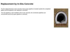
For the replacement by in-situ concrete, the by-pass pipeline is located outside the completed gallery and the pipeline to be replaced is removed. The new pipeline is now installed in the in-situ concrete, the connection pipelines are reconnected and the by-pass pipeline is removed. |
(Image: Possibilities of interior work using gallery techniques (heading) with reference to [Düsse] [Image: S&P GmbH]) |
|
|
|
|
(Image: Inspection) (Image: Leaktightness) The finishing work consists of the following tasks: |
