
|
|
|
(Image: Gravity pipeline) The following materials are commonly used in the manufacturing of gravity, protection and product, pipes. (Table: Commonly used types of new pipelines for the pipe bursting of gravity systems with reference to [DWAM143-15]) |
|
Other pipe types include: (Table: Other types of new pipelines qualified for pipe bursting of gravity systems) |
|
(Image: Gravity pipeline) If polyethylene pipes are to be used, only PE 100 or PE-Xa pipes should be considered. |
Material |
Pipe joint |
External protection |
|
PE 100 |
Connection using a heated butt joint and removal of the weld bead |
External protection is necessary and is to be restored in the weld area. |
|
PE-Xa |
None, only use with coiled pipes, because the welding of PE-Xa is only possible with electrofusion couplers. |
Not required due to the durability … |
|
|
(Image: Rohricon) When using PE pipes for gas and water supply lines, the SDR series listed in the tables below apply. (Table: SDR-series for pipe bursting - Water supply pipelines) (Table: SDR-series for pipe bursting - Gas supply pipelines) |
|
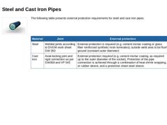
(Image: Rohricon) The following table presents external protection requirements for steel and cast iron pipes. |
Material |
Joint |
External protection |
|
Steel |
Welded joints according to DVGW work sheet GW 350 |
External protection is required (e.g. cement mortar coating or glass fiber reinforced synthetic resin laminates); outside weld area to be flush ground (constant outer diameter) |
|
Cast iron |
Axial-locking joint and rigid connection as per GW368 and … |
|
|
|
|
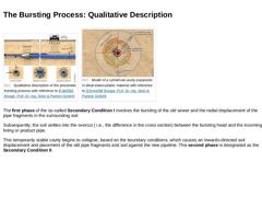
(Image: Qualitative description of the pneumatic bursting process) (Image: Model of a cylindrical cavity expansion in ideal elasto-plastic material with reference to [Zimme88] [Image: S&P GmbH]) The first phase of the so-called Secondary Condition I involves the bursting of the old sewer and the radial displacement of the pipe fragments in the surrounding soil. Subsequently, the soil settles into the overcut ( i.e., the difference in the cross section) … |
|
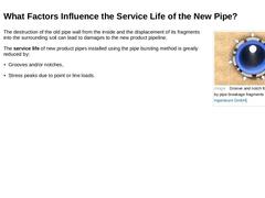
(Image: Groove and notch formation caused by pipe breakage fragments) The destruction of the old pipe wall from the inside and the displacement of its fragments into the surrounding soil can lead to damages to the new product pipeline. The service life of new product pipes installed using the pipe bursting method is greatly reduced by: |
|
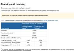
Grooves and notches can occur in all pipe materials. Grooves of up to 10 % of the wall thickness are permissible for pressure pipelines (according to DVGW). Plastic pipes are especially prone to grooving because of their material properties. (Table: Characteristics of the E-modulus (short term and long term) for various materials) 1 The Deutscher Verein des Gas- und Wasserfaches (DVGW) is the German association for gas and water with headquarters in … |
|
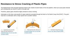
The displacement of the old pipe fragments leads to the creation of point loads on the new pipeline, which can cause peak stresses and consequently can result in cracks in the pipe wall. Therefore, plastic pipes should be highly resistant to stress cracking. Information on the slow crack growth of a pipe material is provided through the Notch or Full Notch Creep Test (FNCT). The point load test in combination with a creep rupture test is another method. |
|
|

|
Peak stresses due to point or line loads occur especially with large pipe fragments. The first theoretical investigations showed stress differences in the pipe of up to 400 % for differently shaped fragments with the same assumed soil stresses [Naneg88]. |
|
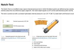
The Notch-Test is a modified creep rupture internal pressure test in which the failure points are defined as four evenly distributed notches about the circumference (apex angle 60°, the notch depth equals to 20 % of the wall thickness) [ISO 13479] The test is carried out with a constant hydrostatic internal pressure in an 175 °F (80 °C) water bath until fracture occurs. (Image: Standstill periods for the Notch-test with reference to [Jürge05] [Image: … |
|
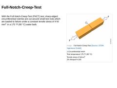
With the Full-Notch-Creep-Test (FNCT) test, sharp-edged circumferential notches are cut around small test rods which are loaded to failure under a constant tensile stress of 4 N/mm2 in a 175 °F (80 °C) water bath. (Image: Full-Notch-Creep-Test) |
|
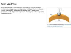
(Image: Point load test with reference to [FI-Hesse] [Image: S&P GmbH]) The point load test for pipes installed on sand bedding using the trenchless method involves applying an external point load to the pipe. The 0.4 in-diameter (10 mm) indenter pin is pressed into the pipe wall up to a defined depth (depression = 0.06 · De) at room temperature. The test piece is then subjected to a creep rupture test. |
|
|
|
|
|
For pipes installed using the bursting method, the following two factors must be considered in the static calculations: -
Lateral loads to the pipeline axis resulting from soil, water, and traffic pressure
-
Axial loads resulting from the pulling-in operation.
|
|
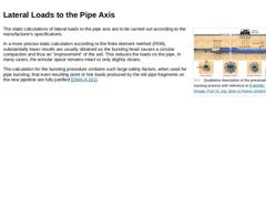
(Image: Qualitative description of the pneumatic bursting process) The static calculations of lateral loads to the pipe axis are to be carried out according to the manufacturer's specifications. In a more precise static calculation according to the finite element method (FEM), substantially lower results are usually obtained as the bursting head causes a circular compaction and thus an "improvement" of the soil. This reduces the loads on the pipe. … |
|
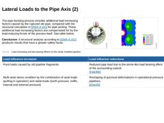
The pipe bursting process includes additional load-increasing factors caused by the ruptured old pipe, compared with the structural calculation in [DWA-A 161] for pipe jacking. These additional load-increasing factors are compensated for by the load-reducing forces of the process itself. See table below. Conclusion: A structural analysis according to [DWA-A 161] produces results that have a greater safety factor. (Image: Point load test with internal … |
|
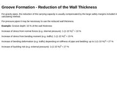
For gravity pipes, the reduction of the carrying capacity is usually compensated by the large safety margins included in the calculating method. For pressure pipes it may be necessary to use the reduced wall thickness. Example: Groove depth: 10 % of the wall thickness Increase of stress from normal forces (e.g. internal pressure): 1-(1-10 %)1 = 10 % Increase of stress from bending moment (e.g. traffic): 1-(1-10 %)2 = 19 % Increase of bending deformation (… |
|
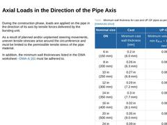
During the construction phase, loads are applied on the pipe in the direction of its axis by tensile forces delivered by the bursting unit. As a result of planned and/or unplanned steering movements, uneven tensile stresses arise around the circumference and must be limited to the permissible tensile stress of the pipe material. In addition, the minimum wall thicknesses listed in the DWA worksheet - [DWA-A 161] must be adhered to. |
|
|
|
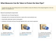
To protect the new pipe, the bursting process can be modified to reduce the influence of the old pipe fragments on the new pipeline in the displaced soil. Measures for protecting the new pipe include: -
Reducing the size of the pipe fragments
-
Using pipes with an increased wall thickness or pipes with an outer protective coat
-
Using double-walled pipe systems (casing pipes)
-
Lubrication of the pipe and fixing of the pipe fragments with a clay cement …
|