|

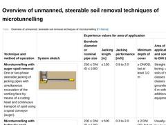
(Table: Overview of unmanned, steerable soil removal techniques of microtunnelling [FI-Steina]) |
|
|
| (Image: Microtunnelling with hydraulic spoil removal in single phase jacking)
|
|
|
|
(Image: Examples of cross sectional shapes of starting shafts in microtunnelling [FI-Herreb] - Circular (open sinking shaft), jacking cylinder arranged parallel to the jacking pipe/to the microtunnelling machine)
|
|
(Image: Entry of the microtunnelling machine into the target shaft)
|
|
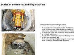
Duties of the microtunnelling machine: - To create the necessary cavity so that the following pipe string can be pressed in with a minimum degree of soil deformation and …
|
|
|
|
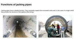
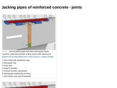
Jacking pipes have a double function: They constantly support the excavated cavity and, in the case of a single shell lining, they provide the structure of the pipeline (final lining). | |
(Image: View into the jacking pipes)
|
(Image: Reinforced concrete jacking pipes)
|
|
|
|
| (Image: Joint of jacking pipes with loose steel guide ring for concrete, reinforced concrete or fibre cement) | | (Image: Joint of jacking pipes with steel guide ring fixed single-sided ) |
|
|
|
(Image: Technical components for microtunnelling with auger spoil removal in single phase jacking)
|
|
(Image: Equipment, possible arrangement of the components on the construction site and space requirement (approximately L × W = 22.0 × 4.0 m) in microtunnelling with auger spoil removal - top view (on the model of the jacking of pipes DN/ID 600, pipe length 2.0 m))
|
|
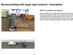
Method of operation and sequence Microtunnelling with auger spoil removal is characterized … |
|
|
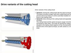
| (Image: Microtunnelling with auger spoil removal in single phase jacking - Variant: driving the cutting head with the spiral conveyor) | Drive variants of the cutting head: - Variant A: driving the cutting head with the spiral conveyor
The spiral conveyors (auger rods) and cutting head are fixed together and are driven by means of a drive assembly installed on the jacking frame in the starting shaft - Variant B: direct driving of the cutting head and separately …
|
|
|
|
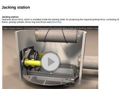
Jacking station:
Hydraulic thrust drive, which is installed inside the starting shaft, for producing the required jacking force, consisting of jacking frame, jacking cylinder, thrust ring and thrust wall (not found). (Video: Operating mode of a jacking station)
|
|
|
|
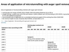
Area of application of microtunnelling methods with auger spoil removal: - nominal pipe size range of DN/ID 250 to DN/ID 1000 and jacking distances of up 150 m
- straight borings, usually loose soil of the soil classes L (stone classes up to S2) according to DIN 18319, in groundwater up to 6 m with additional equipment
- recommended area of application for a controlled mechanical support of the working face ≤ DN/ID 800
- the minimum depth of cover should …
|
|
|
|
(Image: Microtunnelling with hydraulic spoil removal in single phase jacking)
|
|
(Image: Basic equipment, possible arrangement components on the construction site and space requirements (ca. L × B = 35 × 4 m) for microtunnelling with hydraulic spoil removal - plan view (on the model of the jacking of pipes DN/ID 600, pipe length 2.0 m))
|
|
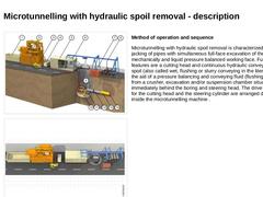
Method of operation and sequence Microtunnelling with hydraulic spoil removal is characterized by the jacking … |
|
|
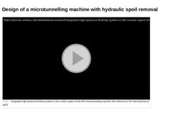
(Video: Integrated high-pressure flushing system in the crusher space of the AVN microtunnelling machine) |
|
|
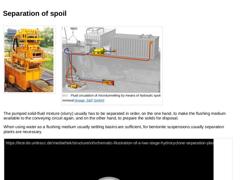
(Image: Separation of the spoil by a separation plant (compact plant MAB 300 with a solids capacity of 75 t/h) [FI-Schau]) (Image: Fluid circulation of microtunnelling by means of hydraulic spoil removal)
The pumped solid-fluid mixture (slurry) usually has to be separated in order, on the one hand, to make the flushing medium available to the conveying circuit again, and on the other hand, to prepare the solids for disposal.
When using water as … |
|
|
|
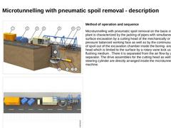
(Image: Microtunnelling with pneumatic spoil removal)
|
|
(Image: Equipment, possible arrangement of the components on the construction site and space requirements (approximately L x W = 34 x 4 m) in microtunnelling with pneumatic spoil removal - plan view (on the model of the jacking of pipes DN/ID 600, pipe length 2.0 m))
|
|
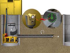
Method of operation and sequence Microtunnelling with pneumatic spoil removal on the basis of a suction plant is characterized … |
|
|
|
|
This lecture is part of the series "Trenchless 101" and serves to provide an overview of steerable trenchless new installation methods for gas, water and wastewater pipelines. |
|
The lecture series "Repair of manholes made of concrete, reinforced concrete and masonry" presents several possibilities for repairing manholes. The second part of the series is about smaller repairs like e.g. the repair of steps, the reparation of surface defects as well as the rehabilitation of joints in masonry sewers. The aim of the lecture is to provide an overview of the implementation of such measures. |

|
|
Steps
The term steps comprises step irons, manhole steps, ladders as well as step boxes. | |
Step iron
Component that can be fixed to the wall of a manhole or to an accessible underground structure in order to provide safe access (with reference to [DINEN13101]). |
|
|
|
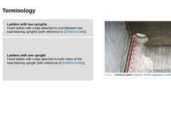
Ladders with two uprights
Fixed ladder with rungs attached to and between two load-bearing uprights (with reference to [DINEN14396]). | (Image: Climbing ladder)
| | |
Ladders with one upright
Fixed ladder with rungs attached to both sides of the load-bearing upright (with reference to [DINEN14396]). |
|
|
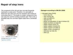
| The compound of the old and new concrete frequently represents a weak point. Therefore, it is advisable to dowel the new step irons into the manhole wall instead of cementing them in. This leads to a better compound of the new step iron and the existing manhole wall. That is why a dowelled step iron can bear higher loads than a cemented one. (Image: Defective (1) or missing (2) step irons) | Damages according to DIN EN 13508 |
|
|
|
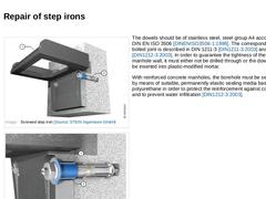
(Image: Screwed step iron)
|
|
(Image: Screwed step iron - detail)
|
The dowels should be of stainless steel, steel group A4 according to DIN EN ISO 3506 [DINENISO3506-1:1998]. The corresponding bolted joint is described in DIN 1211-3 [DIN1211-3:2003] and 1212-3 [DIN1212-3:2003]. In order to guarantee the tightness of the manhole wall, it must either not be drilled through or the dowels must be inserted into plastic-modified mortar. With reinforced … |
|
|
|
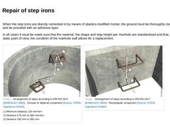
When the step irons are directly cemented in by means of plastics-modified mortar, the ground must be thoroughly cleaned and be provided with an adhesive layer. In all cases it must be made sure that the material, the shape and step height per manhole are standardised and that, from a static point of view, the condition of the manhole wall allows for a replacement. |
(Image: Arrangement of steps according to DIN EN 1917 [DINEN1917a] - Circular or elliptical … |
|
|
|
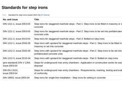
(Table: Standard for step irons (stand 2010-12) [FI-Steina]) |
|

|
(Table: Standards for ladders (stand 2006-07) [FI-Steina]) |
|

|
|

|
|
Measures for the restoration of defective regions in the inside of sewers of concrete, reinforced concrete and pre-stressed concrete have the aim, depending on the selected repair grout, among others of [DAfStBb] : - The maintaining and replacement of the corrosion protection of the reinforcement;
- Replacing / supplementing the concrete cross section with or without requirements of stability;
- Replacing or increasing the resistance of the concrete surface …
|
|
