|

|
The possible consequences of damage of deformation are, according to [ATVM143-1:1989] : - Reduction of the hydraulic effectiveness;
- Blockages;
- Increase of the maintenance effort;
- Crack danger for form pieces at those points that, due to formed branches, kinks, etc. are stiffer than the unstiffened pipe;
- The danger of bulges with very large deformations;
- Tension crack deformation;
- Leaks;
- Cracks;
- Pipe break;
- Collapse.
|
|

|
|
|
|
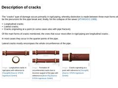
The "cracks" type of damage occurs primarily in rigid piping, whereby distinction is made between three main forms which can be the precursors for the pipe break and, finally, for the collapse of the sewer [ATVM143-1:1989]. - Longitudinal cracks;
- Lateral cracks;
- Cracks originating at a point (in some cases also with pipe fracture).
Of the main forms of cracks mentioned, the ones that occur most often in rigid piping are longitudinal cracks . In most … |
|
|
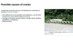
| (Image: Storage of concrete pipes on site)
Irrespective of the type of crack, the following are mentioned as causes [ATVM143-1:1989] : - Non-adherence to the standards and regulations, e.g. EN 1610 [DINEN1610:1997], ATV-A 127E [ATVA127a].
- Damage to the pipes during transport, storage, laying, bedding, backfilling or compacting.
- Effects of wear.
|
|
|
|
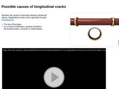
Besides the causes of damage already mentioned above, longitudinal cracks occur specially through (not found): -
The lay of the pipes.
-
As a result of leakiness, position deviation, mechanical wear, corrosion or deformation.
|
(Image: Longitudinal cracks in rigid pipes with reference to [Young84] [Image: S&P GmbH]) |
|
(Video: Development of a longitudinal crack as a result of a leak in a pipe joint with infiltration of groundwater and soil with reference … |
|
|
|
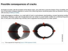
(Image: Formation of circumferential cracks due to incorrect support of the pipe with reference to [Brenn76] [Image: S&P GmbH])
|
|
(Image: Circumferential crack about the whole circumference [FI-KMG])
|
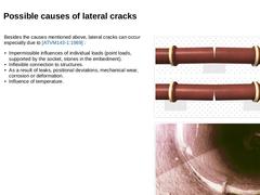
Besides the causes mentioned above, lateral cracks can occur especially due to [ATVM143-1:1989] : - Impermissible influences of individual loads (point loads, supported by the socket, stones in the embedment).
- Inflexible connection to structures.
- As a …
|
|
|
|
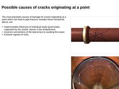
(Image: Cracks orginating at a point with reference to [Young84] [Image: S&P GmbH])
|
|
(Image: Fragmentation of a vitrified clay pipe)
|
The most important causes of damage for cracks originating at a point which can lead to pipe fracture, besides those mentioned above, are: - Impermissible influences of individual loads (point loads, supported by the socket, stones in the embedment).
- Incorrect connections of the lateral due to caulking the sewer.
- Extreme …
|
|
|
|
All shapes of cracks, with the exception of the lateral cracks, carry with them a priori the danger of loss of stability, whereby the time of total failure (collapse) depends on some of the influencing factors mentioned above and can therefore not be predicted with accuracy [Flatt83] [Trott80]. Under advantageous conditions, e.g. small width of crack, no groundwater, good bedding, constant operating conditions (no overloading / flooding), a pipe … |
|

|
|
|
|
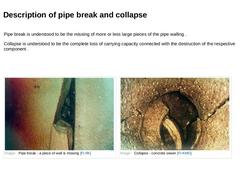
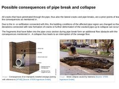
Pipe break is understood to be the missing of more or less large pieces of the pipe walling . Collapse is understood to be the complete loss of carrying capacity connected with the destruction of the respective component . |
(Image: Pipe break - a piece of wall is missing [FI-IfK])
|
(Image: Collapse - concrete sewer [FI-KMG])
|
|
|
|
|
A pipe break is caused by an additional malfunction or changed internal or external loading of an already damaged pipe having a crack or being fractured. Furthermore, according to [ATVM143-1:1989], it occurs due to leaks, mechanical wear, corrosion and cracks. A collapse is the final phase, and the one with the most serious consequences, in the development of the following damage over a period of time. - Leakiness .
- Mechanical wear .
- Corrosion .
- Deformation .
|
|
|
|
All cracks that have penetrated through the pipe, thus also the lateral cracks and pipe breaks, are a priori points of leaks with the consequences as mentioned in . Due to the in- or exfiltration connected with this, the bedding conditions of the affected pipe region are changed so that position deviations connected with new formation of cracks or further deformation of the cracked pipe up to collapse can occur . The fragments that have fallen into … |
|

|
|
|
The aim of this lecture is to provide an overview of the main damage groups, its causes and its consequences. |

|
The lecture series "Repair of manholes made of concrete, reinforced concrete and masonry" presents several possibilities for repairing manholes. The fourth part of the series is about rehabilitation of cracks in manholes by means of injection. The aim of the lecture is to provide an overview of implementation of such measures. |
|
|
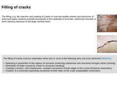
The filling, e.g. the injection and soaking of cracks in man-accessible sewers and structures of drain and sewer systems extends exclusively to the materials of concrete, reinforced concrete or brick masonry because of the large nominal sizes. | |
(Image: Crack formation in the masonry)
|
|
(Image: Crack formation in the concrete)
|
| |
The filling of cracks must be undertaken when one or more of the following aims are to be achieved [Verkehra] : |
|

|
|
The process that is applied for the filling of cracks is differentiated according to the pressures used for inserting the filler into the crack as follows: - Soaking (S): filling without pressure to close the crack;
- Injection (I): filling under pressure using filling nozzles (injection packers) for all the application purposes mentioned above.
| | |
The filler materials for both types of filling are mostly epoxy resins (EP) and polyurethane resins (PUR). |
|

|
|
|
| (Image: Attention!)
|
According to [Verkehra], crack fillers must possess the following properties: - Sufficiently low viscosity;
- High degree of capillary attraction (for reaction resin);
- Good workability;
- Sufficient mixing stability;
- Low shrinkage caused by the reaction;
- Sufficient adhesive strength at the edges of the crack;
- Sufficient strength or expanding strength;
- High degree of ageing resistance;
- Freedom from corrosion producing components;
- Compatibility …
|
|
|
|
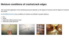
The successful application of the individual processes depends on the degree of moisture and the degree of contamination of the cracks. In [DAfStBb] [Verkehra], four conditions of moisture are defined in greater detail as: - "dry",
- "moist"
- "water flow without pressure and
- "water flow under pressure" .
| |
(Image: Crack - dry)
|
(Image: Crack - moist)
|
(Image: Crack – water-bearing without pressure)
|
(Image: Crack – water-bearing under pressure [FI-Winkl])
|
|
|
|
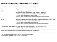
(Table: Distribution of the moisture conditions of cracks/crack edges in accordance with [Verkehra]) |
|
|
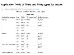
(Table: Regions of application of the fillers for cracks according to [Verkehra]) |
|

|
|
|
|
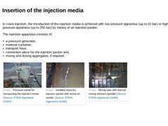
In crack injection, the introduction of the injection media is achieved with low pressure apparatus (up to 20 bar) or high pressure apparatus (up to 250 bar) by means of an injection packer. The injection apparatus consists of: - a pressure generator,
- material container,
- transport hose,
- connection piece for the injection packer and,
- mixing and dosing aggregates, if required.
| |
(Image: Pressure vessel for transporting the injection mortar)
|
(Image: Installed … |
|
|
|
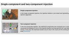
| (Image: Single-component injection in the masonry)
Single-component injection In the single-component injection, the injection medium is pre-mixed and injected by the injection apparatus. | | | (Image: Two-component injection in the masonry)
Two-component injection In the two-component injection, the individual components are conveyed up to a mixer connected immediately in front of the injection packer and injected into the crack after mixing. In this way, … |
|
