|

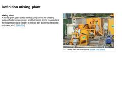
Mixing plant:
A mixing plant (also called mixing unit) serves for creating support fluids (suspensions) and lubricants. In the mixing plant the suspension base (water) is mixed with additives (bentonite, polymers, etc.) [Stein05a]. (Image: Mixing plant with supply pump) |

|

Mixers are available in various sizes and consist mostly of: -
Drive unit (diesel or electrically driven)
-
Mixing container and, if necessary, additional container(s)
-
Drilling fluid pump(s)
Most mixing plants are designed in a modular fashion in order to be able to be placed into service in a relatively simple and flexible fashion with reference to the required capacity. This approach also allows easy combinations with separation plants. (Image: Model … |
|
|
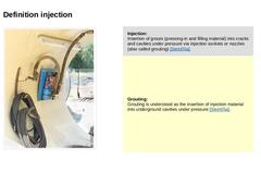
(Image: Lubrication station) |
Injection:
Insertion of grouts (pressing-in and filling material) into cracks and cavities under pressure via injection sockets or nozzles (also called grouting) [Stein05a]. |
|
Grouting:
Grouting is understood as the insertion of injection material into underground cavities under pressure [Stein05a]. |
|
|
|
(Image: Attention!)
The pressing of the lubricant and support medium into the annular gap is also referred to as injection or grouting. The aim is to produce a continuous lubricating film between the pipe and the subsoil, thus reducing the frictional resistance between both. Ideally, the lubricant and support medium should completely fill the annular gap so that the pipe string floats. |
Prerequisites for creating a continuous lubrication are: |
|
|
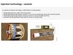
As regards the injection technology, a differentiation is made between: -
Injection/grouting in the region of the boring head
-
Injection/grouting through injection nozzles in a non-man-accessible pipe string with two-phase jacking
-
Injection/grouting through injection nozzles by hand in a man-accessible pipe string
-
Automatic injection/grouting through injection nozzles in the pipe string
(Image: Lubricating the pipe string in the ULTIMATE METHOD (… |
|
|
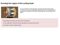
(Image: Lubricating the pipe string in the ULTIMATE METHOD (Bild 9.5.2) with reference to [FI-Kidoh] [Image: S&P GmbH] - Grouting the lubricating and support medium in the boring head region by means of a special distribution ring) For even distribution of the lubrication and support medium about the pipe circumference, some microtunnelling / shield machines have a distribution ring arranged at the periphery of the shield cutting edge with corresponding … |
|
|

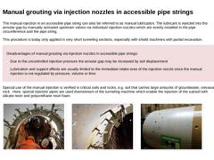
The manual injection in an accessible pipe string can also be referred to as manual lubrication. The lubricant is injected into the annular gap by manually activated upstream valves via individual injection nozzles which are evenly installed in the pipe circumference and the pipe string. This procedure is today only applied in very short tunneling sections, especially with shield machines with partial excavation. Disadvantages of manual grouting via … |
|
|
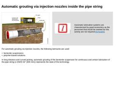
(Image: T.B.K. system for lubricating the jacking string with reference to [FI-TBKa] [Image: S&P GmbH]) |
(Image: Attention!)
Automatic lubrication systems are characterized by good economics as the personnel that would be needed for this activity are not required [Schwa00]. |
|
For automatic grouting via injection nozzles, the following lubricants are used: -
bentonite suspensions
-
polymer-based solutions.
In long distance and curved jacking, automatic … |
|
|
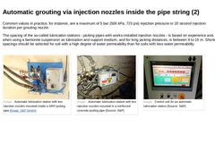
Common values in practice, for instance, are a maximum of 5 bar (500 kPa, 725 psi) injection pressure or 20 second injection duration per grouting nozzle. The spacing of the so-called lubrication stations - jacking pipes with works-installed injection nozzles - is based on experience and, when using a bentonite suspension as lubrication and support medium, and for long jacking distances, is between 9 to 15 m. Example: Every third jacking pipe (3 m) … |
|

|
|
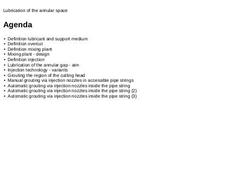
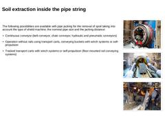
The following possibilities are available with pipe jacking for the removal of spoil taking into account the type of shield machine, the nominal pipe size and the jacking distance: -
Continuous conveyor (belt conveyor, chain conveyor, hydraulic and pneumatic conveyors)
-
Operation without rails using transport carts, conveying buckets with winch systems or self-propulsion
-
Tracked transport carts with winch systems or self-propulsion (floor-mounted …
|
|
|
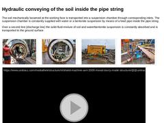
The soil mechanically loosened at the working face is transported into a suspension chamber through corresponding inlets. The suspension chamber is constantly supplied with water or a bentonite suspension by means of a feed pipe inside the pipe string. Over a second line (discharge line) the solid-fluid-mixture of soil and water/bentonite suspension is constantly absorbed and is transported to the ground surface. (Image: Hydraulic soil conveying) (… |
|
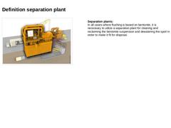
(Image: Technical components in pipe jacking - separation plant) Separation plants:
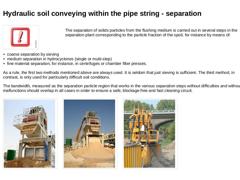
In all cases where flushing is based on bentonite, it is necessary to utilize a separation plant for cleaning and reclaiming the bentonite suspension and dewatering the spoil in order to make it fit for disposal. |
|

The separation of solids particles from the flushing medium is carried out in several steps in the separation plant corresponding to the particle fraction of the spoil, for instance by means of: -
coarse separation by sieving
-
medium separation in hydrocyclones (single or multi-step)
-
fine material separation, for instance, in centrifuges or chamber filter presses.
As a rule, the first two methods mentioned above are always used. … |
|
|
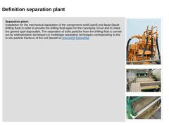
Separation plant:
Installation for the mechanical separation of the components solid (spoil) and liquid (liquid drilling fluid) in order to provide the drilling fluid again for the conveying circuit and to make the gained spoil disposable. The separation of solid particles from the drilling fluid is carried out by sedimentation techniques or multistage separation techniques corresponding to the in-situ particle fractions of the soil (based on [… |
|
|
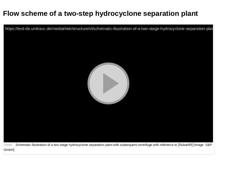
(Video: Schematic illustration of a two-stage hydrocyclone separation plant with subsequent centrifuge) |
|

|
|
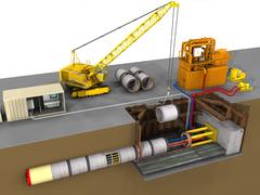
Today, the installation of gas, water and wastewater pipelines is still predominantly carried out using open trenches. In view of the numerous disadvantages associated with this method, it is imperative that trenchless pipeline construction be considered much more strongly in the future than it has been to date as an alternative in the planning and construction of sewers and pipelines.
This module deals in detail with the procedure and the various components. Emphasis is placed on the different types of shield machines, excavation tools, separation systems, the control and steering station, injection/grouting agent and soil extraction and reprocessing.
After completing this module, you will have a sound knowledge of:
- all components of pipe jacking and
- their function and tasks.
|
|

Sewer systems are constantly or temporarily subject to different physical, chemical, bio-chemical and biological stresses. In genaral, damage is caused, on the one hand, by exceeding the normative utility period and, on the other hand, by the different external or internal influencing stresses during operation. The aim of this lecture is to provide an overview of the main damage groups, its causes and its consequences. |
|

| | (Image: Schäden)
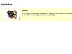
Damage: In the sense of rehabilitation, damage is the condition that is inherent or to be expected in view of the impermissible impairment of functionality. |
|
|

|
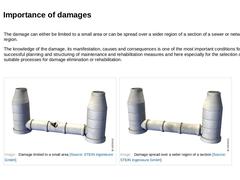
The damage can either be limited to a small area or can be spread over a wider region of a section of a sewer or network region. The knowledge of the damage, its manifestation, causes and consequences is one of the most important conditions for successful planning and structuring of maintenance and rehabilitation measures and here especially for the selection of suitable processes for damage elimination or rehabilitation. |
(Image: Damage limited to … |
|
|

|

|
(Image: Leaking branch connection [FI-IfK])
|
|
(Image: Root ingress)
|
|
(Image: Positional deviation in the longitudinal direction [FI-Jtele])
|
|
(Image: Internal corrosion of a concrete pipe [FI-Jtele])
|
|
(Image: Deformation of an angular-flexible pipe)
|
|
(Image: Fragmentation of a vitrified clay pipe)
|
In the following, the main damage groups that occur in sewer systems and which are mentioned in [ATVM143-1:1989] are: - Leaks ;
- Flow obstacles ;
- Positional …
|
|

|

|
|

|
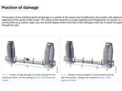
The position of the individual points of damage in a section of the sewer must be defined by the position with reference to the beginning of the section of the sewer. The centre of the manhole is usually regarded as the beginning of a section. In special constructions (e.g. basins, traps, etc.) the section begins at the inner side of the wall (pipe end); this is where the pipeline runs through the wall.. |
(Image: Position of single damages in a section … |
|
|
|

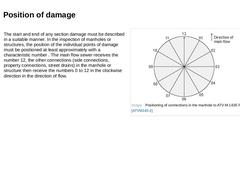
| (Image: Positioning of connections in the manhole to ATV-M 143E Part 2 [ATVM143-2])
The start and end of any section damage must be described in a suitable manner. In the inspection of manholes or structures, the position of the individual points of damage must be positioned at least approximately with a characteristic number . The main flow sewer receives the number 12, the other connections (side connections, property connections, street drains) … |
|