|
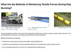
(Image: Target manhole - capstan winch) (Image: Overload protection [Jürge05]) During the pulling-in process, the value of the allowable tensile forces on the new pipe must be strictly enforced. This is accomplished by continuous monitoring (measurement and documentation). Methods of tensile force monitoring: |
|
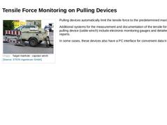
(Image: Target manhole - capstan winch) Pulling devices automatically limit the tensile force to the predetermined maximum value. Additional systems for the measurement and documentation of the tensile forces on the pulling device (cable winch) include electronic monitoring gauges and detailed printout reports. In some cases, these devices also have a PC interface for convenient data transfer. |
|
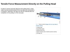
In order to receive real time data from the pulling head, a data cable must be inserted ahead of the new pipe and connected to a computer. Otherwise, the data can only be collected after the completion of the pulling-in of the new pipe. |
|
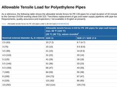
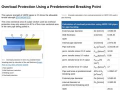
As a reference, the following table shows the allowable tensile forces for PE 100 pipes for a load duration of 30 minutes (according to the German DVGW working sheet GW 323: Trenchless replacement of gas and water supply pipelines with pipe bursting; Requirements, quality assurance and inspections / not available in English at present). (Table: Allowable tensile forces for PE 100 pipes under a 30 min load) |
|
The rupture strength of HDPE pipes is 2.5 times the allowable tensile strength [DVGWGW323]. The cross sectional area of a pipe section used as overload protection may only amount to 40 % of the cross sectional area of the new pipe being pulled in. (Image: Overload protection in form of a predetermined breaking point by reduction of the wall thickness) (Table: Example calculation of an overload protection for HDPE 100 used in pipe bursting) |
|
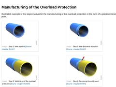
Illustrated example of the steps involved in the manufacturing of the overload protection in the form of a predetermined breaking point. (Image: Step 1: New pipeline) (Image: Step 2: Wall thickness reduction) (Image: Step 3: Welding on of the overload protection) (Image: Step 4: Removing the weld seam) |
|
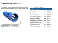
A cross section reduction is obtained by reducing the effective circumference of the pipe or the effective cross-sectional area. (Image: Overload protection in form of a predetermined breaking point by reduction of the effective pipe circumference) (Table: Overload protection) |
|
|

|
Congratulations! You have successfully finished this module. Next you will have the opportunity to review the newly acquired knowledge with an interactive questionnaire. You can still navigate back to any point in the lessons if you wish to review a specific point or subject. Stay curious! |
|
This module focuses on the pipe bursting method as a special method of replacing gas, water, and wastewater pipelines in the same alignment. In addition to the functional principle, the requirements on materials and equipment are presented in detail. After completing this module, you will have a sound knowledge of: - variants of pipe bursting methods;
- effects of the bursting method on the surrounding area;
- methods of tensile force monitoring or limitation.
|
|

Today, supply and discharge lines are still predominantly installed by using the open-cut method: a trench is dug, the lines are installed. Under the protection of an embankment or sheeting and the trench is filled afterwards. In the face of the numerous disadvantages as well as the citizens' growing environmental consciousness in the future it is urgently necessary to take trenchless technology into account much stronger than until today as an alternative … |
|

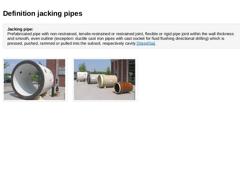
Jacking pipe:
Prefabricated pipe with non-restrained, tensile-restrained or restrained joint, flexible or rigid pipe joint within the wall thickness and smooth, even outline (exception: ductile cast iron pipes with cast socket for fluid flushing directional drilling) which is pressed, pushed, rammed or pulled into the subsoil, respectively cavity [Stein05a]. (Image: Reinforced concrete jacking pipe) (Image: Jacking pipes of different diameters and … |

|

|
|

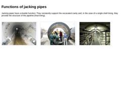
Jacking pipes have a double function: They constantly support the excavated cavity and, in the case of a single shell lining, they provide the structure of the pipeline (final lining). (Image: View into the jacking pipes) (Image: Reinforced concrete jacking pipes) (Image: Example of the final lining of a pipeline tunnel) |
|
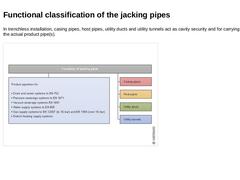
In trenchless installation, casing pipes, host pipes, utility ducts and utility tunnels act as cavity security and for carrying or supporting the actual product pipe(s). (Image: Functional classification of jacking pipes) |
|

|
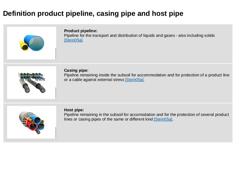
(Image: Product pipes [FI-Steina])
Product pipeline:
Pipeline for the transport and distribution of liquids and gases - also including solids [Stein05a]. |
|
(Image: Casing pipes [FI-Steina])
Casing pipe:
Pipeline remaining inside the subsoil for accommodation and for protection of a product line or a cable against external stress [Stein05a]. |
|
(Image: Bundled installation inside the host pipe [FI-Steina])
Host pipe:
Pipeline remaining in the subsoil … |
|
|

|
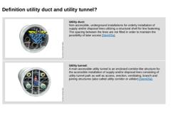
(Image: Utility duct)
Utility duct:
Non-accessible, underground installations for orderly installation of supply and/or disposal lines utilizing a structural shell for line fastening. The spacing between the lines are not filled in order to maintain the possibility of later access [Stein05a]. |
|
(Image: Man-accessible utility tunnel [FI-Steina])
Utility tunnel:
A man-accessible utility tunnel is an enclosed corridor-like structure for the accessible … |
|
|

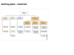
(Image: Materials for jacking pipes) |
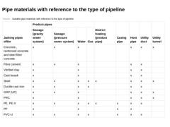
|

(Table: Suitable pipe materials with reference to the type of pipeline) |
|
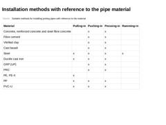
|

|
(Table: Suitable methods for installing jacking pipes with reference to the material) |
|

|
|
(Image: Attention!) |
According to EN 12889, "the installation shall not commence before the following criteria have been agreed between the specifier and installer. These may be obtained from appropriate product standards or from the pipe manufacturer: -
Internal pipe diameter
-
External pipe diameter
-
Pipe length
-
Tolerances on dimensions
-
Safe jacking load or pulling force
-
Type and performance of joints
-
Longitudinal flexibility (acceptable bending …
|
|
|
|
(Image: Attention!) |
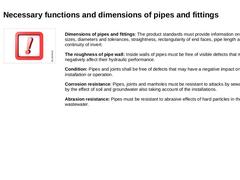
Dimensions of pipes and fittings: The product standards must provide information on nominal sizes, diameters and tolerances, straightness, rectangularity of end faces, pipe length and continuity of invert. The roughness of pipe wall: Inside walls of pipes must be free of visible defects that may negatively affect their hydraulic performance. Condition: Pipes and joints shall be free of defects that may have a negative impact on … |
|
|
|
(Image: Attention!) |
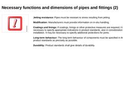
Jetting resistance: Pipes must be resistant to stress resulting from jetting. Modification: Manufacturers must provide information on in-situ handling. Coatings and linings: If coatings, linings or other protective measures are required, it is necessary to specify appropriate indications in product standards, also in consideration of the installation. It may be necessary to specify additional protections for joints. Long-term behaviour: |
|
|
|
(Image: Attention!) |
Load-bearing capacity and stiffness: The following values are particularly necessary for the calculation of the characteristic mechanical behaviour of pipes in dependence of the type of their installation, their use and material: modulus of elasticity, density, tensile strength, yield limit, compressive strength, bending strength, longitudinal compressive strength and vibration amplitude. Temperature: Pipes and joints shall be … |
|
|

|
(Image: Attention!)
The perpendicularity of end faces (perpendicularity of the pipe axis) of jacking pipes for gas, water as well as drains and sewers is of particular importance for transferring the jacking forces when pushing-in, pressing-in or ramming-in and for the dimensioning of the pressure transfer ring [ [DWAA125:2014]]. |
|
|
|
(Image: Measurement of the rectangularity of end faces) |
The perpendicularity of the end surface is defined according … |
|