|
|
|
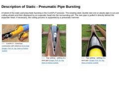
A hybrid of the static and pneumatic bursting is the ConSPLIT process. The existing steel, ductile cast iron or plastic pipe is cut using cutting wheels and then displaced by an expander head into the surrounding soil. The new pipe is pulled in directly behind the expander head. If necessary, the cutting process is supported by a pneumatic hammer. (Image: ConSPLIT - Schematic construction with reference to [FI-PIM] [Image: S&P GmbH]) (Image: Pipe splitting - … |

|
|
|
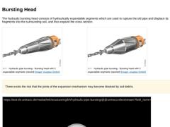
The hydraulic bursting head consists of hydraulically expandable segments which are used to rupture the old pipe and displace its fragments into the surrounding soil, and thus expand the cross section. (Image: Hydraulic pipe bursting - Bursting head with 3 expandable segments (closed)) (Image: Hydraulic pipe bursting - Bursting head with 3 expandable segments (opened)) There exists the risk that the joints of the expansion mechanism may become blocked … |
|
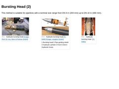
This method is suitable for pipelines with a nominal size range from DN 8 in (200 mm) up to DN 16 in (400 mm). (Image: Hydraulic bursting head) (Image: Hydraulic bursting head) (Image: Hydraulic bursting head [FI-KMG]) |
|
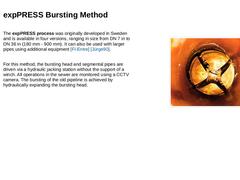
The expPRESS process was originally developed in Sweden and is available in four versions, ranging in size from DN 7 in to DN 36 in (180 mm - 900 mm). It can also be used with larger pipes using additional equipment [FI-Entre] [Jürge90].
For this method, the bursting head and segmental pipes are driven via a hydraulic jacking station without the support of a winch. All operations in the sewer are monitored using a CCTV camera. The bursting of the …
|
|
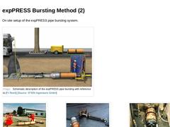
On site setup of the expPRESS pipe bursting system. (Image: Schematic description of the expPRESS pipe bursting with reference to [FI-Teerb] [Image: S&P GmbH]) (Image: expPRESS pipe bursting - Construction site) (Image: expPRESS pipe bursting [FI-Teerb] - Bursting head with hydraulic jacking arrangement) (Image: expPRESS pipe bursting [FI-Teerb] - bursting head in the starting pit) |
|
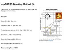
The bursting forces may vary according to the device type and the expansion dimension. |
Example: |
|
Sewer DN 12 in (300 mm) |
|
Segmental pipe De 14 in (355 mm) |
|
Amount of expansion A = 15 % + De = 16 in (410 mm) |
|
Expansion A - DN = 4 in (110 mm) |
|
Expansion/Segment 2 in (55 mm) |
|
Max. bursting force/Segment 180 kN |
|
Total bursting force 360 kN |
(Image: Bursting forces during expPRESS pipe bursting (example) [Jürge05]) |
|
Even though hydraulic pipe bursting is still used internationally, its use in some jurisdictions is limited. The main reason for this is the development of the static pipe bursting. Static pipe bursting does not require additional pit excavation; it uses existing manhole structures in conjunction with properly designed segmental pipes to deliver a much faster, continuous (single-phase) bursting process, as opposed to the hydraulic methods' two-phase (… |

|
|

|
For quality assurance purposes, all the equipment used for the pulling-in of the new pipeline is to be used in accordance with the manufacturer’s recommendations and within the limits of the expected forces. In addition, the contractor must document all relevant working steps, whereby the exact type and scope of the documentation must be defined between the owner and the contractor prior to the commencement of work. It is good … |
|
On-site Documentation The on-site documentation should include at least the following documents: -
Bursting protocol
-
Daily site report
-
Material reception inspection
-
Welding protocol
-
Protocol of the tensile forces during the pulling-in, or rather documentation of the overload protection (if used)
-
Protocols of the leak-tightness (vacuum) testing for sewer pipes and pressure testing for water and gas pipelines
|

|
(Image: Leaktightness) Finishing work and quality testing In order to ensure that the pipelines replaced using the pipe bursting method maintain the same durability and performance as those replaced by open cut, the same finishing work and quality tests apply: Tests: |

|
|

|
Congratulations! You have successfully finished this module. Next you will have the opportunity to review the newly acquired knowledge with an interactive questionnaire. You can navigate back to any point in the modules if you wish to review a specific point or subject. Stay curious! |
|
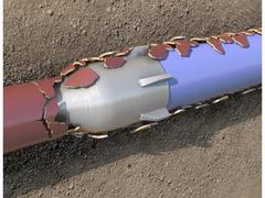
Replacement of supply and disposal pipelines (gas, water, wastewater) means the construction of new pipelines in the same alignment, whereby the new installations incorporate the function of the original pipeline.
This module covers the pipe bursting replacement technique associated with the trenchless construction method.
After completing this module, you will have a sound knowledge of:
- rules and regulations;
- pipe bursting methods, their areas and limits of application and their advantages and disadvantages;
- selection of suitable pipe bursting methods depending on pipe defects and boundary conditions.
|
|
Important: Pipelines and manholes are civil engineering structures in which the proper interaction of components, embedment, initial and final backfill as well as the surrounding soil is the basis for stability and operational safety. Therefore, an understanding of soil (or rock) -
as foundation soil,
-
building material,
-
load and
-
also as a load-bearing and stabilizing material
is an indispensable prerequisite for its use in civil engineering in the … |
|
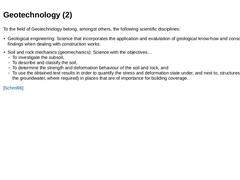
To the field of Geotechnology belong, amongst others, the following scientific disciplines: -
Geological engineering: Science that incorporates the application and evalutation of geological know-how and consolidated findings when dealing with construction works.
-
Soil and rock mechanics (geomechanics): Science with the objectives…
-
To investigate the subsoil,
-
To describe and classify the soil,
-
To determine the strength and deformation behaviour of …
|
|
Owing to its varying behaviour when loaded by structures, [ [EN1997-1:2009]] classifies the subsoil into undisturbed and disturbed soil (subsequently altogether called soil) as well as rock (solid rock). In practice, however, a distinction between undisturbed and disturbed soil is not made. Consequently, all loose material is covered by the collective term “soil”, whereas all solid material is called “rock”. The different types of soil are to be...… |
|
The following slides will look at soil characteristics in greater detail. |
|
|
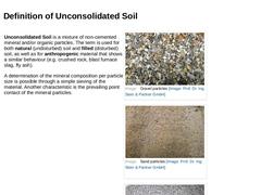
Unconsolidated Soil is a mixture of non-cemented mineral and/or organic particles. The term is used for both natural (undisturbed) soil and filled (disturbed) soil, as well as for anthropogenic material that shows a similar behaviour (e.g. crushed rock, blast furnace slag, fly ash). A determination of the mineral composition per particle size is possible through a simple sieving of the material. Another characteristic is the prevailing point contact … |
|
|
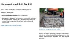
Soil is called backfill, if “it has been artificially placed”. Backfill is divided into: -
Non-compacted fillings of any composition
-
Compacted fillings of non-cohesive or cohesive soil types or inorganic filling material (e. g. building rubble, slag, ore residues), whenever the fillings have been sufficiently compacted
[ [DIN1054:2010]], [EN1997-1:2009] (Image: Compacted backfill under a motorway) Most of the areas below the surface of traffic ways and … |
|
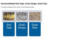
The following categories will be used for a more detailed description: (Image: Unconsolidated soil categories) |

|
|
|
The main types of soil are: -
Non-cohesive soil
-
Cohesive soil
-
Organic (organogenic) soil
-
Vulcanic soil
[[EN ISO 14688:2002]] differentiates -
Very coarse soil;
-
Coarse soil;
-
Fine soil.
These main soil types consists of -
Boulders;
-
Gravel;
-
Sand;
-
Silt and
-
Clay
which are likewise differentiated using particle fractions. |