|
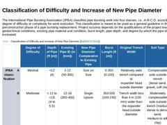
The International Pipe Bursting Association (IPBA) classifies pipe bursting work into four classes, i.e., A-B-C-D, according to the degree of difficulty or complexity for work execution. This classification is meant to be used as a general guideline in the design and preconstruction phase of a pipe bursting replacement. Project success depends on the qualifications of the project team, geotechnical conditions, existing pipe material and condition, … |
|
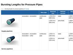
(Table: Bursting lengths for pressure pipelines [FI-Tracta]) |
|
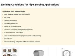
Application limits are affected by: -
Pipe– material, nominal size and condition
-
Soil cover
-
Geological condition
-
Expanding dimension
-
Effects on the environment
-
Distances to crossing or longitudinal pipelines
-
Number of branch connections
-
Major positional deviations (displaced joints / under-bends)
-
Groundwater
-
Concrete bedding and partial or full concrete encasement
(Image: Encasement and special supports of vitrified clay pipes with concrete … |
|
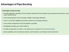
Advantages of pipe bursting: -
Possible application regardless of the host pipe material (with the exception of pre-stressed and reinforced concrete with heavy reinforcement).
-
One bursting operation may encompass multiple nominal pipe diameters.
-
There is no need for additional excavation with the use of existing manholes.
-
Cross section enlargement of the host pipeline is possible.
-
Rehabilitation lengths up to 1000 ft (300 m).
-
Possible compensation …
|
|
Disadvantages of pipe bursting: -
Applications in groundwater are only possible with the use of supporting measures.
-
Possible damage may occur in manhole structures with lower bearing capacities as that of the pushing/pulling forces needed to perform the bursting operation. In such cases, additional access pits need to be excavated.
-
The pipe embedment soil must be displaceable and free of obstacles.
-
Risk of damage to the new pipes during the renewal …
|

|
|
|
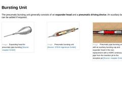
The pneumatic bursting unit generally consists of an expander head and a pneumatic driving device. An auxiliary bursting cap can be added if required. (Image: Expanding head for pneumatic pipe bursting) (Image: Pneumatic bursting unit) (Image: Pneumatic pipe bursting unit with an auxiliary bursting cap and expander head in the rear; replacement with a HDPE continuous pipe from the insertion pit to the reception pit) |
|
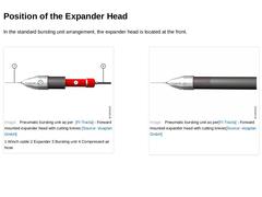
In the standard bursting unit arrangement, the expander head is located at the front. (Image: Pneumatic bursting unit as per [FI-Tracta] - Forward mounted expander head with cutting knives) (Image: Pneumatic bursting unit as per [FI-Tracta] - Forward mounted expander head with cutting knives) |
|
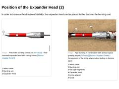
In order to increase the directional stability, the expander head can be placed further back on the bursting unit. (Image: Pneumatic bursting unit as per [FI-Tracta] - Rear mounted expander head with cutting knives) (Image: Pipe bursting in combination with annular space grouting as per [FI-Tracta] - Arrangement of the lining adaptor when pulling-in discrete pipes) |
|
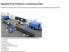
Shown here is a typical setup used for the pulling-in of continuous pipe using the pneumatic pipe bursting method. (Image: Equipment for the pulling-in of a continuous pipe with pneumatic pipe bursting) |
|
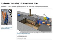
Shown here is a typical pneumatic bursting construction site setup for the pulling in of segmental pipes. (Image: Hydraulic chain tensioner) (Image: Pneumatic pipe bursting in combination with pulling-in of discrete pipes with reference to [FI-Tracta]) |
|
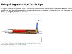
During the pulling-in of segmental pipes, it is necessary to form a tensile unit with the expander head. A tensile-force-tight connection between the pipe segments is established using a chain, which is connected to the expander head. One example of how this can be done is by using a hydraulic chain tensioner. (Image: Fixing of discrete non-tensile pipes during pneumatic pipe bursting using a hydraulic chain tensioner) |
|
|
|
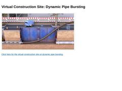
(Image: Virtual construction site: Dynamic Pipe Bursting Screenshot) Click here for the virtual construction site on dynamic pipe bursting. |
|
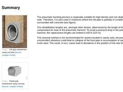
(Image: Full pipe embedment using concrete) (Image: Partial pipe embedment using concrete) The pneumatic bursting process is especially suitable for high-density and non displaceable soils. Therefore, it is also used in instances where the old pipe is partially or completely surrounded with concrete (see figure). The rehabilitation lengths are, amongst other factors, determined by the length of the compressed air hose of the pneumatic hammer. To avoid … |
|
|
|
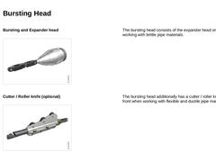
Bursting and Expander head (Image: Bursting and expanding body for static pipe bursting) The bursting head consists of the expander head only, when working with brittle pipe materials. Cutter / Roller knife (optional) (Image: Roller knife for static pipe bursting) The bursting head additionally has a cutter / roller knife at the front when working with flexible and ductile pipe materials. |
|
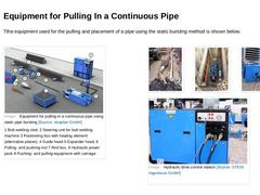
Tthe equipment used for the pulling and placement of a pipe using the static bursting method is shown below. (Image: Equipment for pulling-in a continuous pipe using static pipe bursting) (Image: Static pipe bursting - Expander head) (Image: Static pipe bursting - pushing/pulling carriage) (Image: Pushing- and pulling-equipment with carriage) (Image: Hydraulic drive control station) |
|
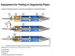
A special clamping system is used for the pulling-in of segmental pipes. (Image: Clamping system for the laying of discrete pipes during static pipe bursting (Burstfix) with reference to [FI-Tracta]) |
|
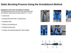
Equipment used in the Grundoburst method
The following machines and tools are used during the Grundoburst static pipe bursting method [FI-Tracta]: (Image: Grundoburst process [FI-Tracta] - Pushing- and pulling-equipment with carriage in the starting excavation) (Image: Grundoburst method-… |
|
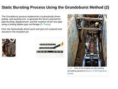
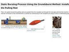
The Grundoburst process implements a hydraulically driven pulling- and pushing unit to generate the forces required for pipe bursting, displacement, and the insertion of the new pipe using a locking ladder-type rod linkage [FI-Tracta]. First, the hydraulically driven push and pull unit is placed and secured in the reception pit. (Image: Pulling- and pushing-rod passing through the manhole) (Image: Installation of the pulling- and pushing-rod [FI-Tracta]) |
|
Then, the guide rod and the pulling rods are pushed from the reception pit through the host pipe and into the insertion pit. The manual connection of the rod elements is carried out continuously in the reception pit using a screw or interlocking type system. (Image: Illustration of the static pipe bursting - pulling-in of a continuous pipe) (Image: Pulling- and pushing-rod passing through the manhole) |
|
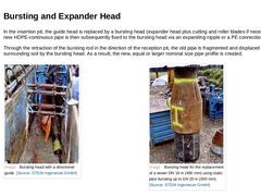
In the insertion pit, the guide head is replaced by a bursting head (expander head plus cutting and roller blades if necessary). The new HDPE-continuous pipe is then subsequently fixed to the bursting head via an expanding nipple or a PE connection adapter. Through the retraction of the bursting rod in the direction of the reception pit, the old pipe is fragmented and displaced into the surrounding soil by the bursting head. As a result, the new, … |
|
Advantages: -
No vibrations
-
No new pit construction is required when using discrete pipe matched to the size of the manhole structure.
-
Can also be used with flexible and ductile pipe materials.
-
The use of the pulling- and pushing-rod assembly along with the vibration free insertion of the new pipeline allows for the application of this method even in sewers and pipelines that would otherwise collapse under the application of pneumatic force.
|
|
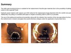
The static pipe bursting process is suitable for the replacement of ductile pipe materials due to the possibility of adding knife/roller cutters to the expander head. Hydraulic power stations with outputs up to 500 t allow for the replacement of pipe diameters DN 40 in (1000 mm) and beyond. Additionally, the pulling in of welded steel pipes in lengths exceeding 3300 ft (1000 m) is possible. The use of the pulling and pushing rod assembly, along with … |