
|
|
(Image: Pros and cons)
(Table: Advantages and disadvantages of microtunnelling with pneumatic spoil removal) |
|
|

|
|
|
(Image: Microtunnelling with spoil removal by other mechanical means (spoil removal by a scraper arrangement)) |
Method of operation and procedure Microtunnelling with scraper spoil removal is marked by pipe jacking with the simultaneous excavation of soil at the work face by means of a cutting head and continuous or discontinuous soil removal with a scraper arrangement. One representative of this group is the Swedish LUNDBY method [FI-Skansb]. |
|
|
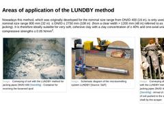
Nowadays this method, which was originally developed for the nominal size range from DN/ID 400 (16 in), is only used in the nominal size range 800 mm (32 in) ≤ DN/ID ≤ 2750 mm (108 in) (from a clear width > 1200 mm (48 in) referred to as manned pipe jacking). It is therefore ideally suitable for very soft, cohesive clay with a clay concentration of ≥ 40% and one-axial uniaxial compressive strengths ≤ 0.05 N/mm2. (Image: Conveying of soil with the … |

|
|
Area of application of the LUNDBY method: -
nominal pipe size range from DN/ID 800 (32 in) up to a clear width < 2750 mm (108 in) and a jacking distance ≤ 150 m (492 ft)
-
usually straight bores; cohesive, saturated soil of classes LBM 1/LBO 1 with N-values ≤ 4
|
|
(Image: Attention!)
Empirical value for the jacking performance in the LUNDBY method: 1.25 to 4.2 m/h (4.1 ft/h to 13.8 ft/h) |
|

|

|
|
|
(Image: Microtunnelling with soil displacement) |
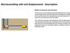
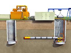
Method of operation and procedure The group of microtunnelling with spoil displacement is characterized by the single-phase jacking of pipes with simultaneous displacement of the soil by means of a displacement and steering head, e.g. no system for removing the soil is provided. The method of operation and equipment of the single-phase microtunnelling method with soil displacement are basically identical … |
|
|
|
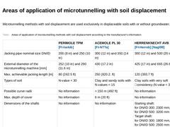
Microtunnelling methods with soil displacement are used exclusively in displaceable soils with or without groundwater. (Table: Areas of application of microtunnelling methods with soil displacement according to the manufacturer's information) |
|

|

|
|
Micro tunnelling refers to unmanned, remote-controlled methods for jacking pipes.
This module covers the various methods, in particular, micro tunnelling with hydraulic, pneumatic, auger and scraper conveyance and soil displacement. The focus is on single- and two-phase micro tunnelling, the technical components in micro tunnelling and areas of application.
After completion of this module, you will have a sound knowledge of:
- spectrum of process technologies;
- machine and control components and
- their functions;
- advantages and disadvantages as well as
- areas of application.
|
|
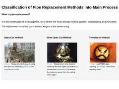
What is pipe replacement?
It is the construction of a new pipeline, on or off the line of an already existing pipeline, incorporating all its functions. The replacement is carried out in section lengths of the sewer using: Open Cut Method (Image: Replacement of sewers using the open cut method) Semi Open Cut Method (Image: Replacement of a masonry sewer by the semi open cut method of construction [Karna94] - Excavating the masonry sewer from the cutting … |
|
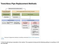
(Image: Overview of replacement methods in trenchless construction) *) Only the pilot boring is steerable in this method. The expansion boring and the following pulling-in or pushing-in of the pipes are non-steerable. |
|
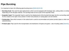
It is important to learn the following pipe bursting terms [DWA-M143-15]: -
Bursting head: Tool used for pipe replacement, which can be equipped with breakage-rails, cutting rollers or similar devices - depending on the old pipe material. The bursting head can be a part of the expander head.
-
Expander head: The expander head is used for the displacement of the bursted host pipe into the surrounding subsoil, and also for the creation of an open cross …
|

|
|

|
The following guidelines can be referenced for pipe bursting method: The International Pipe Bursting Association (IPBA) [Guideline Specifications for the Replacement of Mainline Sewer Pipes By Pipe Bursting ] The Trenchless Technology Center (TTC) [Guidelines for pipe bursting- TTC Report] Plastics Pipe Institute Handbook of PE Pipe Second Edition. Chapter 16, Pipe Bursting. Pipe Bursting Projects (ASCE Manuals and Reports on Engineering Practice No. 112) |

|
The following European standards are also a good reference: Drain and sewer systems outside buildings (2008-04) Trenchless construction and testing of drains and sewers (2000-03) German regulations that address pipe bursting: Rehabilitation of drain and sewer systems outside buildings, Part 15: Replacement of drains and sewer with pipe bursting / not available in English at the present Some other German regulations … |
|
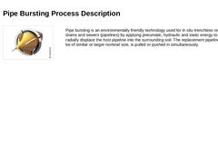
(Image: Replacement by trenchless method) Pipe bursting is an environmentally friendly technology used for in situ trenchless replacement of drains and sewers (pipelines) by applying pneumatic, hydraulic and static energy to fracture and radially displace the host pipeline into the surrounding soil. The replacement pipeline, which can be of similar or larger nominal size, is pulled or pushed in simultaneously. |
|
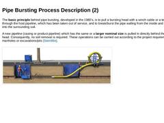
The basic principle behind pipe bursting, developed in the 1980's, is to pull a bursting head with a winch cable or a tension rod through the host pipeline, which has been taken out of service, and to break/burst the pipe walling from the inside and force it radially into the surrounding soil. A new pipeline (casing or product pipeline) which has the same or a larger nominal size is pulled in directly behind the bursting head. Consequently, no soil … |

|
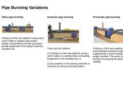
Pipe bursting forces are generated using the following three methods: Static (Video: Static pipe bursting) Hydraulic (Video: Hydraulic pipe bursting) Pneumatic (Video: Pneumatic pipe bursting) |
|
Static pipe bursting
(Image: Illustration of the static pipe bursting - pulling-in of a continuous pipe) Pulling-in of the new pipeline using only a winch cable or pulling chain and/or pulling- and pushing-rod with accordant pulling equipment in the target manhole / reception pit. Hydraulic pipe bursting
(Image: Hydraulic pipe bursting process - pushing-in of discrete pipes) There are two options: (1) Pulling-in of the new pipeline using a winch cable … |
|
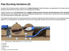
A special form of pipe bursting is referred to as Calibre Bursting. Calibre bursting is an application of the static and dynamic pipe bursting methods which are discussed in the subsequence sections. Calibre bursting uses a bursting head with a smaller outside diameter than the nominal diameter of the old pipeline. Thus, applying force on the old pipe walls, and their subsequent displacement, is limited only to sections with cross-sectional reductions … |
|
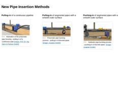
Pulling-in of a continuous pipeline
(Image: Illustration of the pneumatic pipe bursting - pulling-in of a continuous pipe) Pulling-in of segmental pipes with a smooth outer surface (Image: Pneumatic pipe bursting process - pulling-in of discrete pipes) Pushing-in of segmental pipes with a smooth outer surface (Image: Hydraulic pipe bursting process - pushing-in of discrete pipes) |
|
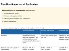
Requirements for the implementation of pipe bursting: -
Circular pipe cross section
-
Preferably brittle pipe materials
-
Sufficiently compacted host pipe embedment
-
Straight pipeline route
(Table: Areas of application for pipe bursting) |
|
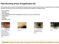
Pipe bursting can be used for the replacement of pipes which are made of various types of materials (with the exception of pre-stressed and reinforced concrete with heavy reinforcement) exhibiting the following issues: -
Pipe breakage
-
Corrosion
-
Flow obstacles
-
Unprofessionally performed rehabilitation processes (e.g. poor workmanship)
-
Deformations
-
Cracks
-
Leakage
-
Mechanical wear
(Image: Longitudinal crack in the pipe joint area resulting in positional … |
|
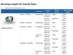
(Table: Bursting lengths - gravity pipelines [FI-Tracta]) |