
|
|
|
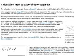
The calculation method according to Sagaseta [Sagas87] is based on the established principles of fluid mechanics. In his analysis, Sagaseta [Sagas87] first assumed an infinitely deep tunnel. This is surrounded by a soil idealized as an incompressible fluid that approximates somewhat to cohesive soil in undrained conditions. Assuming that a deformation vector is known, then the calculation of subsidence caused by a tunnel of finite depth is possible. … |

|
The disadvantage of the method according to Sagaseta [Sagas87] (Abschnitt 15.2.2.1) is in the assumption of the incompressibility of the soil. This means that long-term deformations, which are generated by consolidation or creep, are not considered in the deformation calculation. In order to compensate for this disadvantage, the factor α was introduced which takes into account the change of volume during pipe jacking. With the use of α, radial deformations … |

|
|

|
Included among numerical methods are the Finite Element Method (FEM), the Finite Difference Method (FDM), the Kinematic Element Method (KEM), the Boundary Element Method (BEM) and the Discrete Element Method (DEM). The Finite Element Method is the most widely used method due to its multifaceted possibilities of application and its particular suitability for the depiction of the stress and deformation behaviour of complicated geometries and spatial … |
|
|

|
(Image: Effects of soil deformation on adjoining structures [Attew86]) Critical for the effects of soil deformation on existing structures (Bild 15.3) are the - Deformations during the construction phase
- Total deformations in the final condition
- Differential deformations in the final condition
Differential deformations cause displacement or deformation at existing structures, pipes and traffic surfaces and thus additional loading. In order to estimate … |
|
|
|
Abrasiveness:
The characteristic of soil and rock to cause a larger or smaller amount of wear of the excavation tool during boring (with reference to [Arnol93]) [Stein05a]. Agitator:
Driven rotation body (mixing arm) in front of the rake and suction nozzle inside the invert area of shield machines with fluid-supported working face to avoid the sticking of cohesive soils (e.g. clay) inside the excavation chamber due to dispersion of the suspension (… |

|
With trenchless pipeline construction methods, it is now possible to install cables and pipelines underground, irrespective of the outer diameter or nominal size and the geological and hydrogeological boundary conditions. The wide-ranging technical information in this standard reference book not only helps the user in the planning and execution of pipeline construction measures, but also provides a basis for an economically and technically optimal selection of the process technology. In detail, the technical book deals with the following topics: geotechnical fundamentals and investigations, unmanned, steerable and non-steerable methods (soil displacement methods, pilot pipe jacking, microtunneling, manned methods (pipe jacking), drilling fluids and drilling fluid technology, jacking control, surveying and monitoring, start and target shafts, calculation of jacking pipes, tendering and contract award information, and economic feasibility considerations. |
|
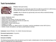
(Image: 105530 - Titelbild Dokumentation) Process: Static pipe bursting Title: Replacement of a vitrified clay sewer DN 12 in (300 mm) and DN 16 in (400 mm) by static pipe bursting with HDPE pipes OD 18 in (450 mm) and OD 20 in (500 mm). Location: Way of cultivation by agriculturally used areas without residential buildings Limiting conditions: -
System: Wastewater sewer
-
Material: Vitrified clay
-
Shape of the cross section: Circular cross section
-
Nominal …
|
|
Machines and equipment: When employing static pipe bursting with the Grundoburst technique by Tractotechnik, Lennestadt the following machines and equipment are predominantly employed: -
Guide head
-
Bursting body (stiff)
-
Expanding body
-
Shear resistant pulling- and pushing-rod also guaranteeing tensile strength
-
Hydraulic power pack
-
Pushing- and pulling-equipment with carriage
To connect the HDPE continuous pipes the following is required: |
|
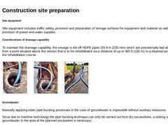
Site equipment Site equipment includes traffic safety, provision and preparation of storage surfaces for equipment and material as well as the provision of power and water supplies. Considerations of drainage capability To maintain the drainage capability, the sewage is led off HDPE pipes DN 8 in (200 mm) which are provisionally laid aboveground from a point situated above the section that is to be rehabilitated via a distance of up to 360 ft (190 m) … |
|
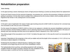
Sewer cleaning In the pipe bursting a sewer cleaning by means of high pressure flushing is carried out directly before the replacement. On the one hand it serves for the removal of deposits, incrustrations etc. and thus the prevention of failures in the bursting- or pulling-in procedure. On the other hand a soiling of the underground by the noxious matters which possibly adhere to the pipe fragments that remain in the underground is to be avoided. Excavations |
|
First the hydraulically driven pushing- and pulling-equipment with carriage for the pulling- and pushing-rod guidance is installed inside the target excavation and is braced. It is telescopable and can be extended in its length from 4 ft to 6 ft (1.2 m to 1.9 m) as a support of the wall of the excavation. Important: A safe pulling- and pushing-rod guidance can only be ensured by a good fixation. (Image: Hydraulic power pack) (Image: Hydraulic pushing- … |
|
The starting and target excavations as well as the small excavations required for the inclusion of the laterals are filled-back directly after the works are completed and the shuttering is re-built. The level of compactness of the filling soil is to amount to Dpr = 97% and is to be proved by a load plate pressure test according to DIN 18134. The "old manholes" that have been dismantled within the scope of rehabilitation preparation are also filled … |
|
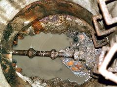
Replacement of a vitrified clay sewer DN 300 and DN 400 using the static pipe bursting method and insertion of PE-HD pipes DA 450 and DA 500. |
|
Today, supply and discharge lines are still predominantly installed by using the open-cut method: a trench is dug, the lines are installed. Under the protection of an embankment or sheeting and the trench is filled afterwards. In the face of the numerous disadvantages as well as the citizens' growing environmental consciousness in the future it is urgently necessary to take trenchless technology into account much stronger than until today as an alternative … |
|
|
(Image: Unmanned techniques) |
|
(Image: Steerable techniques) |
|
Microtunnelling:
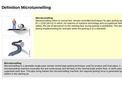
Microtunnelling refers to unmanned, remote-controlled techniques for pipe jacking (jacking pipe ID < 1200 (48 in)) in which, for reasons of machine technology and occupational health and safety, the use of personnel on the working face during jacking is prohibited. This also applies during troubleshooting for example when the jacking is at a standstill. |
|
Microtunnelling |
|
|
|
(Image: Unmanned techniques) |
|
(Image: Steerable techniques) |
|
(Image: Soil removal techniques) |
|
(Image: Soil displacement techniques) |
|
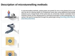
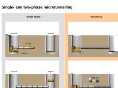
In microtunnelling methods, jacking pipes are jacked (in one or two phases) from a starting shaft with the aid of a jacking station (in exceptional cases also using additional intermediate jacking stations) up to a target shaft. At the same time an unmanned, remote controlled microtunnelling machine carries out … |
|
|
|
Single-phase |
(Image: Single-phase jacking - Jacking) |
|
(Image: Single-phase jacking - Completed pipeline) |
|
Two-phase |
(Image: Two-phase jacking - Phase 1) |
|
(Image: Two-phase pipe jacking - Phase 2) |
|
|
|
|
(Image: Soil removal techniques) |
|
(Image: Microtunnelling with auger spoil removal) |
|
(Image: Microtunnelling with hydraulic spoil removal) |
|
(Image: Microtunnelling with pneumatic spoil removal) |
|
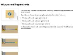
The unmanned, steerable microtunnelling techniques employed base generally on the principle of soil removal. Depending on the way of conveying the spoil, it is differentiated between: |
|
|
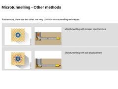
Furthermore, there are two other, not very common microtunnelling techniques. |
|
(Image: Soil removal techniques) |
(Image: Microtunnelling with spoil removal by other mechanical means (spoil removal by a scraper arrangement)) |
Microtunnelling with scraper spoil removal |
|
(Image: Soil displacement techniques) |
(Image: Microtunnelling with soil displacement) |
Microtunnelling with soil displacement |
|

|

|
|
|
(Image: Technical components in microtunnelling) |
|
(Image: Equipment, possible arrangement of the technical components on the construction site and space requirement in microtunnelling with auger spoil removal - top view) |
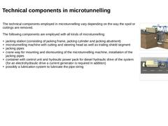
The technical components employed in microtunnelling vary depending on the way the spoil or cuttings are removed. The following components are employed with all kinds of microtunnelling: -
jacking station (consisting of jacking frame, …
|
|