
|
|
|
Non-removable (lost) linings (Bild 12.4) are understood in the case of trenchless installation to be covering, bracing and anchoring structures which are left partially or wholly in the subsoil after completion of the jacking or construction works. Thus, this method of lining offers the ability to use the structural shell as a network structure for operation and servicing in the form of a single or double shell lining (Abschnitt 12.2). The disadvantages … |
|
|
|
In closed sinking shafts, a massive pressure retaining cover with the side cutters forms a working chamber open to the bottom through which the water for sinking is forced out by means of compressed air. Air locks and shaft pipes make the working chamber accessible and the excavation base open for loosening and conveying the soil (Abschnitt 9.2.1.2.3) [Linge97]. This form of sinking shaft [Linge97] [Breck84] [Niema70] is relatively seldom used in trenchless … |
|
|
(Image: Construction of a 22 m deep starting shaft (inside diameter 5.0 m) as an open sinking shaft of reinforced concrete in the in-cast concreting method [Adams99])
|
|
(Image: "Hanging shaft" when sinking in soft soil (dimensions L x W x H = 8.8 m x 4.5 m x 20 m) [FI-Skansa] - Support and pressing construction)
|
|
(Image: "Hanging shaft" when sinking in soft soil (dimensions L x W x H = 8.8 m x 4.5 m x 20 m) [FI-Skansa] - View into the completed … |
|
|
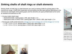
(Image: Sinking shafts of prefabricated rectangular reinforced concrete elements - Upper parts of shafts (left) and lower parts of shafts with steel cutters (hanging) [FI-Meyera]) Sinking shafts of shaft rings or shaft elements are used as starting shafts for jacking pipes in the nominal size range ≤ DN/ID 800 (especially microtunnelling and pilot pipe jacking) depending on the nominal size and length of the jacking pipes and the elements are quasi … |
|
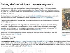
(Image: Sinking shaft (internal diameter 5.0 m) of bolted reinforced concrete segments [Clark92]) For construction sites with difficult access and for shaft diameters > DN/ID 3200 and/or greater sinking depths (> 10 m), the factory prefabricated sinking shafts of shaft rings or shaft elements can no longer be transported due to their great dimensions (Abschnitt 9.1) and for structural reasons can no longer be inserted. Besides the open sinking shafts … |
|
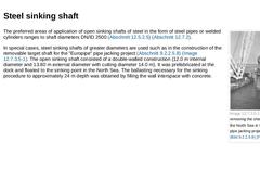
(Image: Target shaft for removing the shield machine from the North Sea in the "Europipe" pipe jacking project (Bild 9.2.2.5.8) (Bild 9.2.2.5.8) [FI-Herreb]) The preferred areas of application of open sinking shafts of steel in the form of steel pipes or welded cylinders ranges to shaft diameters DN/ID 2500 (Abschnitt 12.5.2.5) (Abschnitt 12.7.2). In special cases, steel sinking shafts of greater diameters are used such as in the construction of the … |

|
|

|
|
|
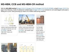
With the MS-HBM method (Bild 12.7.1) (Bild 12.7.1) (Bild 12.7.1) [FI-KCMM], a shaft (Bild 12.7.1), called a core pipe in the following, made of waterproof, welded pipes (Bild 12.7.1) or screwed (in non-waterlogged soils) pipes and core drilling bit is sunk, rotary-pressing by means of a mobile shaft boring machine. | (Image: The MS-HBM method: shaft boring method with core pipes of steel for use in soil [FI-KCMM] - Type MS-HBM-2500 ? layout and dimensions) |
|
|
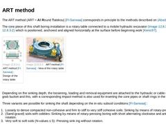
The ART method (ART = All Round Tatekou) [FI-Sanwaa] corresponds in principle to the methods described on Abschnitt 12.7.1. The core piece of this shaft boring installation is a rotary table connected to a mobile hydraulic excavator (Bild 12.7.2) (Bild 12.7.2) which is positioned, anchored and aligned horizontally at the surface before beginning work [Kenic97]. | (Image: ART method [FI-Sanwaa] - Design of the rotary table) | (Image: ART method [FI-Sanwaa] - … |
|

|
|
|
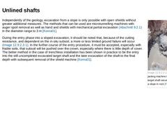
(Image: Entry of a jacking machine into an unlined target shaft secured by means of a slope in rock [FI-Herreb]) Independently of the geology, excavation from a slope is only possible with open shields without greater additional measures. The methods that can be used are microtunnelling machines with auger spoil removal as well as hand and shields with mechanical partial excavation (Abschnitt 9.2.1) in the diameter range to 3 m [Konra01]. During the … |
|
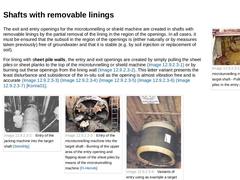
(Image: Entry of the microtunnelling machine into the target shaft - Pulling of the sheet piles in the entry area [Stein05a]) The exit and entry openings for the microtunnelling or shield machine are created in shafts with removable linings by the partial removal of the lining in the region of the openings. In all cases, it must be ensured that the subsoil in the region of the openings is (either naturally or by measures taken previously) free of … |
|
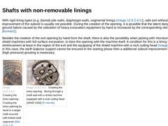
With rigid lining types (e.g. (bored) pile walls, diaphragm walls, segmental linings (Bild 12.8.1.3)), safe exit without additional improvement of the subsoil is usually not possible. During the creation of the opening, it is possible that the latent danger of existing ground failure caused by the utilization of heavy excavation equipment by hand is increased by the corresponding vibrations [Konra01]. Besides the creation of the exit opening by hand … |
|
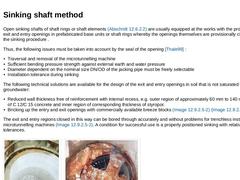
Open sinking shafts of shaft rings or shaft elements (Abschnitt 12.6.2.2) are usually equipped at the works with the project-specific exit and entry openings in prefabricated base units or shaft rings whereby the openings themselves are provisionally closed during the sinking procedure . Thus, the following issues must be taken into account by the seal of the opening [Thale99] : - Traversal and removal of the microtunnelling machine
- Sufficient bending …
|
|
|
|
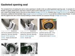
The simplest form of sealing the exit or entry openings in shafts is the so-called gasketed opening seal . It consists of a single or double or duplex elastomeric seal that is fixed in place at the shaft wall (Bild 12.8.2.1) (Bild 12.8.2.1). The seal fixture may use a steel fixed flange fixed to the exit or entry sleeve (Bild 12.8.2.1), a bolted ring (Bild 12.8.2.1) or similar and, if necessary, additional intermediate rings (Bild 12.8.2.1) (Bild … |
|
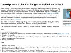
(Image: Exit lock in the form of a closed pressure chamber flanged to the starting shaft [Stein05a]) In this variant, a pressure resistant steel container is fastened to the inside wall of the shaft and this is closed to the inside wall of the shaft by means of a blind flange and at the outer side by means of a removable lining in the form of sheet piles or the special prepared lining region for traversal of the microtunnelling or shield machine in … |
|
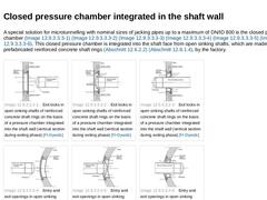
A special solution for microtunnelling with nominal sizes of jacking pipes up to a maximum of DN/ID 800 is the closed pressure chamber (Bild 12.8.2.2.2) (Bild 12.8.2.2.2) (Bild 12.8.2.2.2) (Bild 12.8.2.2.2) (Bild 12.8.2.2.2) (Bild 12.8.2.2.2). This closed pressure chamber is integrated into the shaft face from open sinking shafts, which are made of prefabricated reinforced concrete shaft rings (Abschnitt 12.6.2.2) (Abschnitt 12.8.1.4), by the factory. |
|
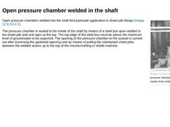
(Image: Open pressure chamber welded to the inside of the shaft) Open pressure chambers welded into the shaft find particular application in sheet pile linings (Bild 12.8.2.2.3). The pressure chamber is sealed to the inside of the shaft by means of a steel box open welded to the sheet pile wall and open at the top. The top edge of the steel box must be above the maximum level of groundwater to be expected. The opening of the pressure chamber to the … |
|
|
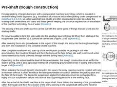
(Image: Possibilities for creating pre-shafts in the form of trough constructions [Konra01] - Sheet pile profiles binding into an aquifuging, cohesive soil strata (LB))
|
|
(Image: Possibilities for creating pre-shafts in the form of trough constructions [Konra01] - Sealing wall with jet grouting base sealing)
|
|
(Image: Entry procedure in a pre-shaft of sheet piles with binding into an aquifuging soil strata [Konra01])
|
For pipe jacking of larger … |
|
|
|
When using closed sinking shafts (Abschnitt 12.6.1) as starting or target shaft, it is feasible at the exit and entry phases to use the existing compressed air equipment (Bild 12.8.2.3). In this case, the pressurized shaft acts as a compressed air chamber for supporting the in-situ groundwater pressure when opening the exit or entry opening. The exit and entry openings are previously created during the construction of the reinforced concrete sinking … |