|
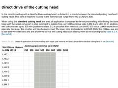
In the microtunnelling with a directly driven cutting head, a distinction is made between the standard cutting head and the rock cutting head. This type of machine is used in the nominal size range from 400 ≤ DN/ID ≤ 800. When using the standard cutting head, the area of application (compared to the microtunnelling with driving the standard cutting head with the spiral conveyor) is also extended to cobble-free, very stiff cohesive soils (LBM 3 and … |
|
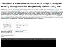
No further aid measures are necessary when installing a rotary vane lock at the end of the spiral conveyor (Bild 8.2.3.3.1) or a rotating feed apparatus (Bild 8.2.3.3.1). The use of sealing systems only cause unimportant pressure losses. During the necessary interruption of procedures of the conveying equipment, for instance in the course of installing a new jacking pipe in the starting shaft, the hermetic closure of the spiral conveyor end must … |
|
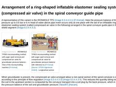
A representative of this variant is the IRONMOLE TPS (Bild 8.2.3.3.2) [FI-Komat]. Here the pressure balance of the groundwater pressure up to 0.6 bar or 6 m head of water above pipe invert occurs only at one place with the aid of an inflatable ring shaped elastomer sealing system (called compressed air valve in the following) arranged in the spiral conveyer guide pipe in the trailing shield segment (Bild 8.2.3.3.2). |
(Image: IRONMOLE TP95S microtunnelling … |
|
|
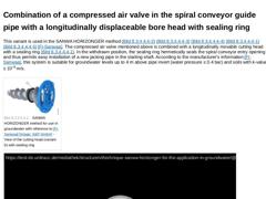
This variant is used in the SANWA HORIZONGER method (Bild 8.2.3.2) (Bild 8.2.3.2) (Bild 8.2.3.2) (Bild 8.2.3.2) (Bild 8.2.3.2) [FI-Sanwaa]. The compressed air valve mentioned above is combined with a longitudinally movable cutting head with a sealing ring (Bild 8.2.3.3.3). In the withdrawn position, the sealing ring hermetically seals the spiral conveyor entry opening and thus permits easy installation of a new jacking pipe in the starting shaft. … |
|
This variant, for instance in the SANWA PRESSTONE method, is provided with an eccentric cone crusher and is a variant of the HORIZONGER method modified for use in groundwater [FI-Sanwaa]. For maintaining the required supporting pressure at the working face, it uses a spade that is movable along the longitudinal axis at the end of the respective spiral in combination with the injection of a bentonite suspension in the region of the spiral conveyor … |
|
Microtunnelling methods with auger spoil removal can only be used in saturated or water bearing soils to a limited extent. The reason for this can be found in the design of the conveyor arrangement, which, in the design of the auger string as well as the spiral conveyors, does not represent a closed system and therefore permits the flow of the groundwater from the working face to the starting shaft. According to manufacturer information, with cohesive … |
|
According to ATV-A 125E [ATVA125:1996], the area of application of the microtunnelling with auger spoil removal ranges from nominal pipe size DN/ID 250 to DN/ID 1000 and for jacking distances up to 150 m [Eulen97] [Geres98] in cohesive and non-cohesive soils. They can only be used to a limited extent in groundwater without auxiliary measures (Abschnitt 8.2.3.3). To achieve controlled mechanical pressure balance of the working face, reference [Becke96] … |
|
|
(Image: Microtunnelling with auger spoil removal in single phase jacking)
|
|
(Image: Microtunnelling machine with auger spoil removal and direct drive of the cutting head (Variant B) - Longitudinal section [FI-Herreb])
|
Microtunnelling with auger spoil removal, also known as (Bild 8.2) auger microtunnelling is characterized by single or two-phase jacking (Abschnitt 3) of pipes (Abschnitt 13) in soils (in exceptional cases also in rock mass) with … |
|
As regards the jacking of the pipes, the method of operation of the single-phase microtunnelling method with hydraulic spoil removal corresponds in principle with the microtunnelling with auger spoil removal (Abschnitt 8.2). For geometrical reasons, use is made of the so-called slurry principle (Abschnitt 9.2.2.5) for the liquid pressure balance of the working face where the required pressure of the balance and conveying liquid (flushing fluid) is … |
|
| (Image: Eccentric cone crusher [FI-MGF]) | | (Image: Stone crusher arrangement of the UNCLEMOLE with reference to [FI-Isekib] [Image: S&P GmbH]) | | (Image: Stone crusher arrangement of the UNCLEMOLE [FI-Isekib]) | | (Image: Pipe-Replacer [FI-NLW] - Eccentric breaker disc; the coned breaker disc is placed eccentrically on the main drive shaft) | | (Image: Sticking of the cutting head and the crushing chamber by clumps of clay [FI-Herreb]) |
Most of the microtunnelling … |
|
|
(Image: Basic equipment (plan view) for microtunnelling with hydraulic spoil removal with reference to [FI-Hazem] [Image: S&P GmbH])
|
|
(Image: Site arrangement of an AVN 600 with separation plant [FI-Herreb])
|
An overview of the required basic equipment for microtunnelling with hydraulic spoil removal is shown in Bild 8.3.1.2 and Bild 8.3.1.2. In principle, the required basic equipment for microtunnelling with hydraulic spoil removal consists of … |
|
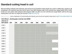
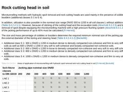
Microtunnelling methods with hydraulic spoil removal and standard cutting heads are used in cobble-free, loosely to densely compacted, non-cohesive and very soft or soft to very stiff cohesive soils in the nominal size range DN/ID 200 to 1200. An exception to this is in very soft to soft cohesive soils (classes LBM 1 to LBO 1) in the nominal size range DN/ID 1200 as the support of the working face can then no longer be ensured (Tabelle 8.3.1.3.1)… |
|
Microtunnelling methods with hydraulic spoil removal and rock cutting heads are used mainly in the presence of cobbles and boulders (additional classes S 1 to S 4). In addition, utilization is also possible in the nominal size range DN/ID 300 to 1200 in all soil classes L without additional class S (Tabelle 8.3.1.3.1). However, because of sticking of the cutting head and the excavation tools (Abschnitt 9.2.2.5) and too little removal of spoil despite … |
|
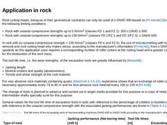
Rock cutting heads, because of their geometrical contraints can only be used of ≥ DN/ID 300 based on [FI-Herreb] [Becke96] under the following limiting conditions: - Rock with uniaxial compressive strengths up to 5 N/mm2 (classes FD 1 and FZ 1): 300 ≤ DN/ID ≤ 500.
- Rock with uniaxial compressive strengths up to 100 N/mm2 (classes FD 1/FZ 1 and FD 3/FZ 3): ≥ DN/ID 600
In rock with an uniaxial compressive strength > 100 N/mm2 (classes FD 4 and FZ 4), the … |
|
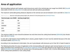
Microtunnelling methods with hydraulic spoil removal are used in the nominal pipe size range from DN/ID 200 [Suzuk97] up to a clear width of 1200 mm (Abschnitt 3) in soils and rock with and without groundwater. The maximum achievable jacking distances depend on the nominal size and are between 120 m and 500 m (Tabelle 8.3.1.3). (Table: Maximum achievable jacking lengths with reference to the jacking pipe size [Kollm00] [FI-Rasa]) The minimum depth of … |
|
|
|
|
(Image: DYWIDAG-Stahlrohrgelenkschild (steel pipe articulated shield) with reference to [FI-Dywidd] [Image: S&P GmbH] - Working process step 1: Jacking the trailing pipes (DN/OD 860))
|
|
(Image: DYWIDAG-Stahlrohrgelenkschild (steel pipe articulated shield) with reference to [FI-Dywidd] [Image: S&P GmbH] - Working process step 2: Installing the pipeline by means of pushing in with simultaneous pushing out the trailing pipe string in the target shaft … |
|
|
(Image: Principle of the withdrawal technique of a microtunnelling machine with hydraulic spoil removal) It is not possible in all cases (e.g. in the later creation of drainage pipes in waste dumps and contaminated areas or the creation of pipe arches [Camp01]) to excavate target shafts, for instance, for the removal of microtunnelling machines. In such cases, only microtunnelling machines that are suitable for the jacking of blind borings can be … |
|
|
(Image: Microtunnelling with hydraulic spoil removal in single phase jacking)
|
|
(Image: Microtunnelling machine with hydraulic spoil removal - Longitudinal section (method AVN) [FI-Herreb])
|
The microtunnelling method with hydraulic spoil removal [ATVA125:1996] [Stein89g] [Stein96a] [Stein98d] (Bild 8.3) in EN 12889 [DINEN12889:2000] is also called slurry shield microtunnelling. It is characterized by single or two-phase jacking (Abschnitt 3) …
|
|
In the method with pneumatic conveying based on a suction plant, the spoil from the excavation and crusher chamber moves through an opening into a rotary vane lock arranged in front of the suction nozzle (Bild 8.4.1.1.1) (Bild 8.4.1.1.1). From there, with the aid of the air flushing medium, it travels through a suction line up to the surface to the preliminary separator where it is separated from the airflow (Bild 8.4.1.1.1) (Bild 8.4.1.1.1). The … |
|
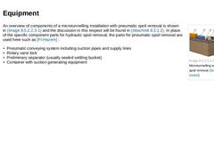
(Image: Microtunnelling with pneumatic spoil removal) An overview of components of a microtunnelling installation with pneumatic spoil removal is shown in (Bild 8.4.1.1.2) and the discussion in this respect will be found in Abschnitt 8.3.1.2. In place of the specific component parts for hydraulic spoil removal, the parts for pneumatic spoil removal are used here such as [FI-Hazem] : - Pneumatic conveying system including suction pipes and supply lines
|
|
Microtunnelling methods with pneumatic spoil removal are used in Europe by the following manufacturers: HAZEMAG & EPR [FI-Hazem] in the nominal size range DN/ID 400 to DN/ID 1200 in soils and rock with groundwater pressures to a maximum of 0.8 bar (8 m head of water above pipe crown), by HERRENKNECHT [FI-Herreb] in the nominal size range DN/ID 600 to DN/ID 1000 in groundwater-free "dry" soils and rock. Because of the method of operation, these microtunnelling … |

|
The HAZEMAG & EPR-P [FI-Hazem] and HERRENKNECHT AVP method [FI-Herreb] are German developments. The former machine can be used for microtunnelling with hydraulic spoil removal (MTB-S) as well as with pneumatic spoil removal (MTB-P) by simply re-equipping the conveying system. |
|
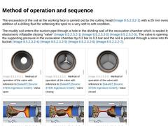
The excavation of the soil at the working face is carried out by the cutting head (Bild 8.4.1.2) with a 25 mm overcut with the addition of a drilling fluid for softening the spoil to a very soft to soft condition. The muddy soil enters the suction pipe through a hole in the dividing wall of the excavation chamber which is sealed by means of an elastomeric inflatable closing "valve" (Bild 8.4.1.2.1) (Bild 8.4.1.2.1) (Bild 8.4.1.2.1). The valve is opening … |
|
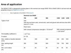
The DEINO TYPE is designed for jacking pipes in the nominal size range DN/ID 700 to DN/ID 1500 in soil and rock with the properties shown in Tabelle 8.4.1.2.2. (Table: Area of application of the DEINO TYPE [Sakai97]) The jacking distances depend on the nominal size of the jacking pipe and are up to 800 m. Curve radii of 30 m or more can be jacked (Tabelle 8.4.1.2.2). The minimum depth of cover should be ≥ OD of the cutting head according to manufacturer'… |