|
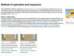
(Image: IRONMOLE TP80-2 method [FI-Komat]) The IRONMOLE TP80-2 method [FI-Komat] (Bild 7.2.2.1) is a two-phase method (Abschnitt 3). Its features are that in the pilot boring it works according to the soil displacement as well as the soil removal principle and, during the subsequent reaming boring, it works according to the soil removal principle (Tabelle 7.2). Phase 1: Pilot boring
In the first phase, the steered boring is first established from the … |
|
A review of the basic equipment of the IRONMOLE TP80-2 is shown in Bild 7.2.2.1. The main components are the same as for ACEMOLE PC 10 MP (Abschnitt 7.2.1). Further equipment required is: - Reamer with corresponding external diameter for each nominal pipe size in place of the expander,
- Conveying equipment, settling container or separation plant depending on the machine variant.
|
|
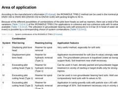
According to the manufacturer's information [FI-Komat], the IRONMOLE TP80-2 method can be used in the nominal pipe size range DN/ID 150 to DN/ID 900 (DN/OD 232 to DN/OD 1100) with jacking lengths to 50 m. Because of the different possibilities of combinations of the pilot bore heads as well as reamers, there are a total of five method variations (Tabelle 7.2.2.3) of the IRONMOLE TP80-2 for applications in cohesive and non-cohesive soils with N-values … |
|
|
|
|
(Image: EARTH ARROW with reference to [FI-Nitto] [Image: S&P GmbH])
|
|
(Image: Design of the reamer with reference to [FI-Nitto] [Image: S&P GmbH])
|
|
(Image: EARTH ARROW method: dimensions of the jacking station [FI-Nitto])
|
|
(Image: Clear dimensions of the starting and target shafts for a jacking pipe length of 2.43 m in the EARTH ARROW method [FI-Nitto])
|
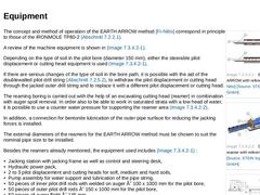
The concept and method of operation of the EARTH ARROW method [FI-Nitto] correspond in principle … |
|
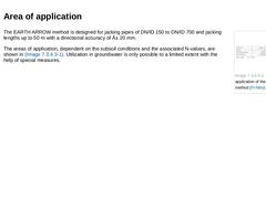
(Image: Areas of application of the EARTH ARROW method [FI-Nitto]) The EARTH ARROW method is designed for jacking pipes of DN/ID 150 to DN/ID 700 and jacking lengths up to 50 m with a directional accuracy of ± 20 mm. The areas of application, dependent on the subsoil conditions and the associated N-values, are shown in Bild 7.2.3.2. Utilization in groundwater is only possible to a limited extent with the help of special measures. |
|
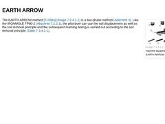
(Image: Overview of the machine equipment for the EARTH ARROW [FI-Nitto]) The EARTH ARROW method [FI-Nitto] (Bild 7.2.3) is a two-phase method (Abschnitt 3). Like the IRONMOLE TP80-2 (Abschnitt 7.2.2.1), the pilot bore can use the soil displacement as well as the soil removal principle and the subsequent reaming boring is carried out according to the soil removal principle (Tabelle 7.2). |
|
|
(Image: BM 500 - method sequence with the two-phase pilot pipe jacking with refernece to [Niede98] - Pilot boring)
|
|
(Image: BM 500 - method sequence with the two-phase pilot pipe jacking with refernece to [Niede98] - Reaming boring)
|
|
(Image: Reamer in the BM 500 method [FI-Bohrt])
|
|
(Image: Pilot cutting head in the BM 500 method [FI-Bohrt])
|
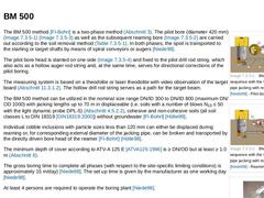
The BM 500 method [FI-Bohrt] is a two-phase method (Abschnitt 3). The pilot bore (diameter 420 mm) (Bild … |
|
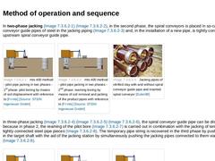
In two-phase jacking (Bild 7.2.5.1) (Bild 7.2.5.1), in the second phase, the spiral conveyors is placed in so-called spiral conveyor guide pipes of steel in the jacking piping (Bild 7.2.5.1) and, in the installation of a new pipe, is tightly connected to the upstream spiral conveyor guide pipe. |
(Image: mts 400 method - pilot pipe jacking in two phases - 1st phase: pilot boring by means of soil displacement with reference to [FI-mts] [Image: S&P GmbH])
|
|
|
|
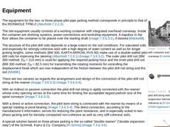
(Image: Site equipment with container and integrated craneway [FI-Wirthb])
|
|
(Image: Double walled pilot drill string with bentonite suspension lubrication with reference to [FI-Schmi] [Image: S&P GmbH])
|
|
(Image: Types of reamers with reference to [FI-Schmi] [Image: S&P GmbH] - Indirect or passive connection)
|
|
(Image: Types of reamers with reference to [FI-Schmi] [Image: S&P GmbH] - Direct or active connection)
|
|
(Image: Principle of the "double … |
|
|
Because of the relatively small outside diameter of the pilot bore string (82.5 mm to 115 mm, depending on the manufacturer), the pilot boring can be carried out in all displaceable (i.e. soils with a number of blows of N10 ≤ 50 with the light dynamic probe DPL-5) (Abschnitt 4.5.2.2) homogeneous cohesive and non-cohesive soils. If the surrounding soil permits, individual cobble inclusions with a particle diameter ≤ 80 mm can be displaced in the 1… |
|
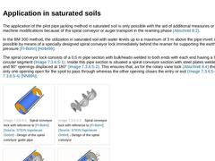
The application of the pilot pipe jacking method in saturated soil is only possible with the aid of additional measures or by means of machine modifications because of the spiral conveyor or auger transport in the reaming phase (Abschnitt 8.2). In the BM 300 method, the utilization in saturated soil with water levels up to a maximum of 3 m above the pipe invert is made possible by means of a specially designed spiral conveyor lock immediately behind … |
|
The methods mts 400 [FI-mts], RVS 80 [FI-Wirthb], BM 300 and BM 400 [FI-Bohrt], as well as PBA 85 [FI-Schmi] are twophase and/or three-phase methods (Abschnitt 3). The steered pilot boring is carried out in all cases according to the principle of soil displacement and the subsequent reaming according to the principle of soil removal with transport of spoil to the starting shaft with the aid of a spiral conveyor (Tabelle 7.2) [Braue99]. |
|
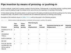
In these methods, a pilot bore is always created in the first phase. Subsequently, in two-phase jacking, a jacking station is used to press or jack the piping through the subsoil at the same time as the expansion or reaming of the boring. In three-phase jacking, the jacking station is used to push in the piping simultaneously with the pushing out of an temporary pipe. In exceptional cases, this phase is also combined with the additional expansion … |
|
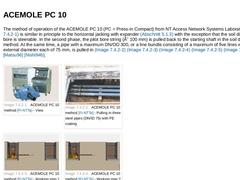
The method of operation of the ACEMOLE PC 10 (PC = Press-in Compact) from NT Access Network Systems Laboratories (Bild 7.3.1) is similar in principle to the horizontal jacking with expander (Abschnitt 5.1.3) with the exception that the soil displacing pilot bore is steerable. In the second phase, the pilot bore string (Ø 100 mm) is pulled back to the starting shaft in the soil displacement method. At the same time, a pipe with a maximum DN/OD 300, … |
|
|
(Image: Method sequence in the first and second phase [FI-Weiss] - Phase 1: Steered pilot boring)
|
|
(Image: Method sequence in the first and second phase [FI-Weiss] - Phase 2: Pulling in the anchor pulling string)
|
|
(Image: Phase 3: Reaming boring with flushing head and simultaneous pulling-in of the pipe string [FI-Weiss])
|
The special features of the two-phase hydros®STAR method [FI-Weiss] is the pulling-in of piping in the second phase with … |
|
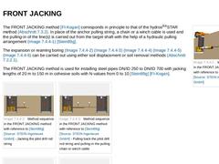
(Image: Working principle in the FRONT JACKING method with reference to [Stein89g] [Image: S&P GmbH]) The FRONT JACKING method [FI-Kogan] corresponds in principle to that of the hydros®STAR method (Abschnitt 7.3.2). In place of the anchor pulling string, a chain or a winch cable is used and the pulling-in of the line(s) is carried out from the target shaft with the help of a hydraulic pulling arrangement (Bild 7.3.3) [Stein89g]. The expansion or reaming … |
|
Pilot pipe jacking in combination with the pulling-in of the piping in the second phase (also called "front jacking" [Stein89g]) is not mentioned in EN 12889 [DINEN12889:2000] as a variant method. In the case of trenchless installation, this term will be understood to refer to methods in which, in the first phase, a pilot bore is established and, in the second phase, the line(s) is (are) pulled in with the aid of pulling forces at the same time as … |
|
|
|
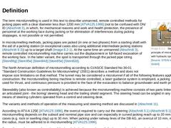
(Image: Sketch of the principle of microtunnelling (here with hydraulic spoil removal)) The term microtunnelling is used in this text to describe unmanned, remote controlled methods for jacking pipes with a clear diameter less than 1200 mm [ATVA125:1996] (not to be confused with DN/ID (Abschnitt 3), in which, for mechanical reasons and work and health protection, the presence of personnel at the working face during jacking or for elimination of interferences … |
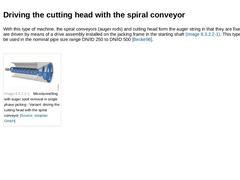
|
With this type of machine, the spiral conveyors (auger rods) and cutting head form the auger string in that they are fixed together and are driven by means of a drive assembly installed on the jacking frame in the starting shaft (Bild 8.2.1.1). This type of drive can be used in the nominal pipe size range DN/ID 250 to DN/ID 500 [Becke96]. (Image: Microtunnelling with auger spoil removal in single phase jacking - Variant: driving the cutting head with … |
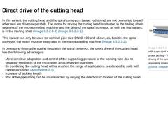
|
(Image: Microtunnelling with auger spoil removal in single phase jacking - Variant: direct driving of the cutting head and separately driven spiral conveyor) In this variant, the cutting head and the spiral conveyors (auger rod string) are not connected to each other and are driven separately. The motor for driving the cutting head is situated in the trailing shield segment of the microtunnelling machine and the drive of the spiral conveyor, as with … |
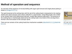
|
(Image: Microtunnelling with auger spoil removal) An overview of the sequence of microtunnelling with auger spoil removal and single phase jacking is shown in Bild 8.2.1. The spoil loosened at the working face with the aid of the cutting head is transported to the starting shaft by the spiral conveyor and is there collected in a spoil bucket. Using lifting tackle, this is lifted to the surface when full at determined intervals, usually after jacking … |
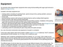
|
|
(Image: Equipment with mobile short container (dieselhydraulic drive) [FI-Wirthb])
|
|
(Image: Example of cutting head driven with the spiral conveyor [FI-Herreb])
|
|
(Image: Example of cutting head driven with the spiral conveyor [FI-Wirthb])
|
|
(Image: Example of cutting head driven with the spiral conveyor [Becke96])
|
|
(Image: Example of cutting head driven with the spiral conveyor [FI-Schrö])
|
An overview of the required basic equipment when using … |
|
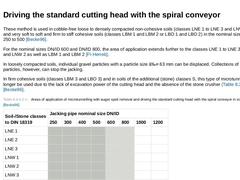
These method is used in cobble-free loose to densely compacted non-cohesive soils (classes LNE 1 to LNE 3 and LNW 1 to LNW 3) and very soft to soft and firm to stiff cohesive soils (classes LBM 1 and LBM 2 or LBO 1 and LBO 2) in the nominal sizes from DN/ID 250 to 500 [Becke96]. For the nominal sizes DN/ID 600 and DN/ID 800, the area of application extends further to the classes LNE 1 to LNE 3 or LNW 1 and LNW 2 as well as LBM 1 and LBM 2 [FI-Herreb]. |