|
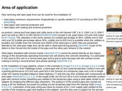
In the two-phase horizontal jacking with installation, pipes with DN/OD ≤ 100 and jacking lengths ≤ 15 m [ATVA125:1996] can be jacked [Jenne92] [Stein89g] through compactable, loose to medium dense displaceable, non-cohesive and very soft to firm and firm to stiff cohesive soils of soil classes LNE 1 to 2 or LNW 1 to 2 as well as LBO 1 and 2 or LBM 1 and 2 to DIN 18319 [DIN18319:2000]. In contrast to the DH, this process is suitable for all water-… |
|
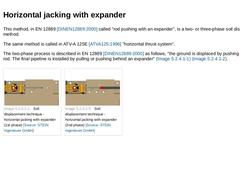
This method, in EN 12889 [DINEN12889:2000] called "rod pushing with an expander", is a two- or three-phase soil displacement method. The same method is called in ATV-A 125E [ATVA125:1996] "horizontal thrust system". The two-phase process is described in EN 12889 [DINEN12889:2000] as follows, "the ground is displaced by pushing a rigid pilot rod. The final pipeline is installed by pulling or pushing behind an expander" (Bild 5.1.3) (Bild 5.1.3). |
|
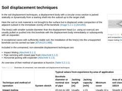
(Image: Soil displacement and compaction when using impact moling [Stein89g]) In the soil displacement techniques, a displacement body with a circular cross section is jacked statically or dynamically from a starting shaft into the subsoil up to the target shaft. Here the soil or rock material is not brought to the surface but is displaced under compaction of the adjacent subsoil in the immediate vicinity of the borehole (Bild 5.1) [Arnol93]. The line(… |
|
|
(Image: Removal cone [FI-Tracta])
|
|
(Image: Removal adaptor [FI-Tracta])
|
|
(Image: Discontinously soil removal from a pipe DN/ID 1400 using a mini excavator [FI-Tracta])
|
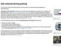
The removal of the soil during jacking can be carried out continuously during jacking or discontinuously. Continuous soil removal is carried out with the aid of an additional removal cone or adaptor with side openings (Bild 5.2.1.1.1.1) (Bild 5.2.1.1.1.1), which is situated between … |
|
|
(Image: Principle of compressed air removal with a scraper - Pipe seal with valves for air or water supply [FI-Essig])
|
|
(Image: Principle of compressed air removal with a scraper - Sketch of the principle [FI-Tracta])
|
|
(Image: Principle of compressed air removal with a scraper - Soil core pressed out with compressed air [FI-Tracta])
|
Besides, the methods mentioned above, the following alternatives are available for removal of the soil core in … |
|
During jacking of the open steel pipe, the in situ soil is forced into the inside of the pipe and the air in it is displaced through slots at the head of the horizontal ram or the open adaptor. As already mentioned, the soil core thus formed can be removed continuously, discontinuously at suitable intervals (Abschnitt 5.2.1.1.1.1) or after completion of the jacking (Abschnitt 5.2.1.1.1.2). |
|
|
(Image: Examples of the support of steel pipes in the starting shaft when installing the horizontal ram [FI-Tractb])
|
|
(Image: Aligning the horizontal ram in the starting shaft using an air lifting bag - System sketch [FI-Tractb])
|
|
(Image: Aligning the horizontal ram in the starting shaft using an air lifting bag - Horizontal ram aligned and connected to the steel pipe by means of adaptor and tensioning belt [FI-Tracta])
|
|
(Image: Variant of the … |
|
|
The discussion in Abschnitt 5.1.1.2 will apply in principle regarding the equipment for pipe ramming with open pipe front and the compressed air supply. Also in this case, no abutment is required in the starting shaft for absorbing the reaction forces. The following equipment is required for pipe rammings with open pipe front: - Displacement hammer (Abschnitt 5.1.1) with impact elements (impact cone and/or impact segments) or, for larger diameters, a …
|
|
| (Image: Two-phase jacking of a gas pipe [FI-Tracta] - Lubricating the pipe string with a bentonite suspension) | | (Image: Two-phase jacking of a gas pipe [FI-Tracta] - Pulling out the temporary pipe while simultaneously pulling in the product pipe) | | (Image: Two-phase jacking of a gas pipe [FI-Tracta] - Product pipe after completion of the jacking works) | | (Image: Jacking a steel pipe DN 3000 with a length of 37 m with a horizontal ram - View of the … |
|
|
Pipe ramming with open pipe front is described in EN 12889 [DINEN12889:2000] as, "pipe ramming/pushing with an open ended pipe," and defined as follows: "Technique of forming a bore by driving a steel casing with an open end using a percussive hammer or pushing device. The spoil is removed by augering, jetting, compressed air or high pressure water." Internationally the short terms "pipe ramming" or "impact ramming" are usual as well. In practice, … |
|
The utilization of uncased auger boring machines begins from a starting shaft secured according to DIN 4124 [DIN4124:2002] (Abschnitt 12.1). The minimum length of the starting shaft is determined by the length of the base frame and the selected length of the auger rod string (0.5 m or 1.0 m). After alignment (analogous to method of operation of impact moling (Abschnitt 5.1.1.1)) and anchoring the machine either with the use of an abutment plate, earth … |
|
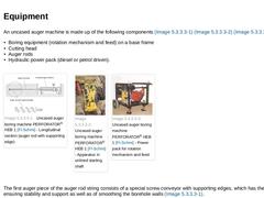
An uncased auger machine is made up of the following components (Bild 5.2.2.2) (Bild 5.2.2.2) (Bild 5.2.2.2) : - Boring equipment (rotation mechanism and feed) on a base frame
- Cutting head
- Auger rods
- Hydraulic power pack (diesel or petrol driven).
(Image: Uncased auger boring machine PERFORATOR® HEB 1 [FI-Schmi] - Longitudinal section (auger rod with supporting edge)) | (Image: Uncased auger boring machine PERFORATOR® HEB 1 [FI-Schmi] - Apparatus in unlined … |
|
|
Uncased auger boring is used in homogenous, stable soils free of groundwater (soil classes LBO 2 and 3 and LBM 2 and 3 as well as LNE 2 and 3 and LNW 2 and 3 to DIN 18319 [DIN18319:2000]) for uncased straight line borings in the diameter range 90 mm to 220 mm [FI-Schmi]. The stability of the in situ subsoil for this application case must be assured not only as regards the support of the borehole walls against subsequent collapse and borehole deformation, … |

|
In uncased auger boring, the subsoil is bored through in a rotating manner by means of an auger bore string and the loosened spoil is conveyed from the uncased borehole to the starting shaft. The uncased auger boring is not mentioned in EN 12889 [DINEN12889:2000] or ATV-A 125E [ATVA125:1996]. The uncased auger machine is based on the auger boring without casing (Bild 5.2.2) [Arnol93] and presents the simplest method variant of all boring techniques … |
|
(Image: Principle of design of an auger boring plant [Stein89g]) The principal elements of a auger boring plant are shown in Bild 5.2.3.1. In this installation, the base frame positioned in the starting shaft carries the apparatus for the auger boring assembly consisting of hydraulically driven jacking cylinders as well as a drive for the auger string. The jacking cylinders are supported at the back against the thrust bridge fixed to the base frame. … |
|
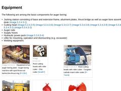
The following are among the basic components for auger boring: - Jacking station consisting of base and extension frame, abutment plates, thrust bridge as well as auger bore assembly with control desk (Bild 5.2.3.2)
- Cutting head (Bild 5.2.3.2) (Bild 5.2.3.2) (Bild 5.2.3.2) (Bild 5.2.3.2) (Bild 5.2.3.2) (Bild 5.2.3.2) (Bild 5.2.3.2) (Bild 5.2.3.2)
- Auger rods
- Supply hoses
- Hydraulic power pack (Bild 5.2.3.2)
- Lifter for mounting, operation and dismounting (…
|
|
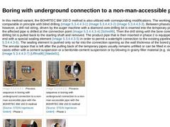
A particular method variant of auger boring is the socalled blind or dead-end drilling. This boring does not end in a target shaft or other cavity. A representative of this technique is the BOHRTEC BM 150 D method [FI-Bohrt]. The boring process is divided into the following phases: - Phase 1: Jacking the temporary pipes of steel up to the target point.
- Phase 2: Pulling back the drill string and pushing in the product pipe (the lead end of the first pipe …
|
|
In this method variant, the BOHRTEC BM 150 D method is also utilized with corresponding modifications. The working phases are comparable in principle with blind drilling (Bild 5.2.3.3.2) (Bild 5.2.3.3.2) (Bild 5.2.3.3.2). Between phases 1 and 2, however, a drill rod string, driven by the auger machine with a diamond core drilling bit is inserted into the temporary pipe string and the affected pipe is drilled at the connection point (Bild 5.2.3.3.2) |
|
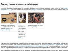
In special applications, especially in the making of laterals to man-accessible sewers (≥ DN/ID 1200), the pipe (Bild 5.2.3.3.3) (Bild 5.2.3.3.3) as well as other secured cavaties (Bild 5.2.3.3.3) can take over the function of the starting shaft . | (Image: Boring a lateral from a man-accessible sewer (BOHRTEC BM 150 DT method)) | (Image: BOHRTEC BM 150 DT method - boring a lateral from a man-accessible sewer - Boring at an angle of 90° [FI-Bohrt]) | …
|

|
Auger boring can be used in all soil classes L to DIN 18319 [DIN18319:2000] up to rock (rock classes FD 1/FZ 1 to FD 4/FZ 4 to DIN 18319 [DIN18319:2000]) for the installation of steel pipes with a nominal size DN/OD ≤ 1600 mm and jacking lengths of maximum 100 m. When used in groundwater, auxiliary measures are necessary. The jacking length depends on the nominal pipe size, on the subsoil and the resulting skin friction as well as the technical parameters … |
|
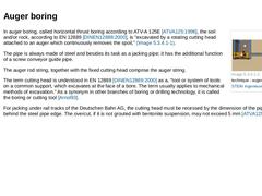
(Image: Soil removal technique - auger boring) In auger boring, called horizontal thrust boring according to ATV-A 125E [ATVA125:1996], the soil and/or rock, according to EN 12889 [DINEN12889:2000], is "excavated by a rotating cutting head attached to an auger which continuously removes the spoil," (Bild 5.2.3). The pipe is always made of steel and besides its task as a jacking pipe; it has the additional function of a screw conveyor guide pipe. The … |
|
In trenchless technology for installation of cables and pipes, two types of machines are in use at present and these differ in their method of operation and sequence as follows: - Hammer drilling with eccentric cutting head (Abschnitt 5.2.4.2)
- Hammer drilling with concentric cutting head (Abschnitt 5.2.4.3)
The cutting heads are equipped with hard metal cutting edges or tungsten carbide inserts. Both rotary-percussive process variants possess the option … |

|
|
(Image: Down-the-hole hammer with eccentric cutting head and steel piping [FI-Krupp])
|
|
(Image: Down-the-hole hammer with eccentric cutting head and reamer and steel pipe with reference to [Arnol93] [Image: S&P GmbH] - Principle of operation)
|
|
(Image: Down-the-hole hammer with eccentric cutting head and reamer and steel piping - View [FI-MGF])
|
The hammer drilling with eccentric cutting head corresponds largely to the auger boring method (Abschnitt … |
|
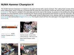
The NUMA Hammer Champion H is based on dry spoil removal with a spiral conveyor. The cutting head consists of two parts, the inner cutting head, which is directly connected with the down-the hole hammer (centre bit) and an outer cutting ring (ring bit) (Bild 5.2.4.3.1). The ring bit is welded to the steel pipe point at the start of the boring. Its purpose is the profiling (recutting) of the borehole to its final diameter and for transferring the … |

|
In the ROTEX Symmetrix HZ-system (Bild 5.2.4.3.2), the spoil removal is achieved by means of an auger. As for the NUMA Hammer Champion H, the percussion cutting head is made in two parts (pilot bit and ring bit). However, in this case, the outer ring bit welded to the steel pipe can rotate (Bild 5.2.4.3.2) (Bild 5.2.4.3.2). (Image: Hammer drilling with ROTEX Symmetrix HZ 406 system (borehole diameter 432 mm) over a length of 193 m [FI-Rotex] - View … |