
|
In the process of Electromagnetic Induction (EMI), the subsoil is subjected to an alternating field by means of a coil and this induces a secondary field. This, again, superimposes itself on the exciting field. The resulting field is measured by a receiver coil. The frequency range used in the EMI method ranges from 10 Hz to 2 MHz. The coil spacings vary from a few metres to about 100 m. Electromagnetic methods react very sensitively to zones of enhanced … |
|
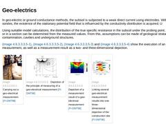
In geo-electric or ground conductance methods, the subsoil is subjected to a weak direct current using electrodes. With the aid of sondes, the existence of the stationary potential field that is influenced by the conductivity distribution is acquired. U Using suitable model calculations, the distribution of the true specific resistance in the subsoil under the probing point, along a profile or in a section can be determined from the measured values. … |
|
|
(Image: Schematic depiction of the principle of the geo-radar method of measurement with reference to [FI-Trote] [Image: S&P GmbH])
|
|
(Image: Reflected signal of a measurement by means of a georadar in a single point depiction with reference to [FI-Trote])
|
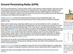
With Ground Penetrating or Probing Radar (GPR) a high-frequency electromagnetic radio wave pulse is transmitted into the subsoil by means of a so-called antenna. The signal is partly reflected … |

|
The selective borings and drillings and probings usual today do not always satisfy the requirements of subsoil investigation for trenchless installations. According to DIN 18319 [DIN18319:2000], in order to make the best choice of the method for an application with respect to the boring head design, working face support, subsoil transport and separation (Abschnitt 10.9.3), it is necessary to possess detailed soil information over the complete length … |

|
"Indirect exploration involves geophysical methods and techniques (e.g. soundings) used to determine the physical properties of soil and rock which, when correlated with geotechnical parameters, allow conclusions to be drawn regarding the ground (remark: subsoil) conditions" [DIN4020:2003] [DIN4020:2003]. Among the indirect exploration methods are: - Probings (dynamic and pressure probings) (Abschnitt 4.5.2.2.1) ;
- Geophysical methods (Abschnitt 4.5.2.2.2).
|
|
|
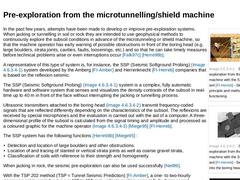
(Image: Seismic pre-exploration from the shield machine with the SSP system in soil [FI-Herreb] - Sketch of the principle and method of functioning)
|
|
(Image: Seismic pre-exploration from the shield machine with the SSP system in soil [FI-Herreb] - Sensors installed into the boring head)
|
|
(Image: Seismic pre-exploration from the shield machine with the SSP system in soil [FI-Herreb] - Processed graphic with cobbles or boulders intruded in the subsoil)
|
|

|
Which exploration and investigation methods are to be used in a particular application case should be subject to consultation between an experienced engineer with detailed knowledge of trenchless installations and an expert on local soil conditions ("geotechnical specialist" [DIN4020:2003] [DIN4020:2003]) before specifying geotechnical investigations for a trenchless project. The investigation of the subsoil is not subject to any whim of the geotechnical … |
|
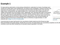
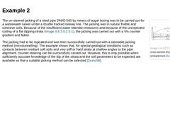
(Image: Geologic cross section through the bank [Zezsc99]) For pipe jacking underneath a mining railway embankment, exploration by means of probings were carried out on both sides of the embankment. According to this investigation, cohesive soil was to be expected in the jacking region. The groundwater level was below the base levels of the start and target shafts. During jacking, after approximately 30 m, coarse gravel with a large proportion of … |
|
(Image: Geologic cross section through the railway embankment [Zezsc99]) The un-steered jacking of a steel pipe DN/ID 500 by means of auger boring was to be carried out for a wastewater sewer under a double tracked railway line. The jacking was in natural friable and cohesive soils. Because of the insufficient water retention measures and because of the unexpected cutting of a flat dipping strata (Bild 4.5.2.5.1.2), the jacking was carried out with … |

|
In the following, two examples (Abschnitt 4.5.2.5.1.1) (Abschnitt 4.5.2.5.1.2) of trenchless installation by jacking [Zezsc99] will be given to demonstrate the difficulties in the interpretation of exploration results with reference to the subsoil. The examples show that sometimes, despite adherence to the exploration requirements to DIN 4020 [DIN4020:2003] [DIN4020:2003], unforeseen difficulties can crop up. |
|
The results of the geotechnical investigation as well as the laboratory analyses must be determined accurately by the geotechnical specialist and described in a geotechnical report. According to DIN 4020 [DIN4020:2003] [DIN4020:2003], the geotechnical report comprises the presentation and evaluation of the results of all geotechnical investigations and the conclusions to be drawn with regard to the project and the construction work, and is meant to … |
|
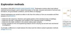
(Image: Exploration and investigation methods within the scope of geotechnical investigations) According to DIN 4020 [DIN4020:2003] [DIN4020:2003], "Exploration involves direct and indirect methods and techniques used to obtain information on the type, structure and extent of soil and rock formations, the groundwater conditions, and the effects of seepage." Subsoil explorations are carried out either in-situ from the surface or from an excavation and … |
|
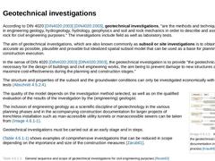
According to DIN 4020 [DIN4020:2003] [DIN4020:2003], geotechnical investigations, "are the methods and techniques employed in engineering geology, hydrogeology, hydrology, geophysics and soil and rock mechanics in order to describe and assess soil and rock for civil engineering purposes." The investigations include field as well as laboratory tests. The aim of geotechnical investigations, which are also known commonly as subsoil or site investigations |

|
|
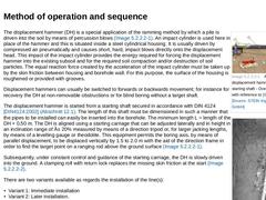
|
|
(Image: Aligning the displacement hammer in the starting shaft - Overview sketch with reference to [Stein89g] [Image: S&P GmbH])
|
|
(Image: Aligning the displacement hammer in the starting shaft - Displacement hammer aligned on starting carriage [FI-Tracta])
|
|
(Image: Clamping cone for immediate pulling in of the piping [Stein89g] [FI-Tracta])
|
|
(Image: Pulling-in cable in connection with a clamping plate for pulling in the pipe - Sketch of the principle [… |
|
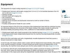
|
| (Image: Equipment of a displacement hammer as example from the GRUNDOMAT [FI-Tracta]) | | (Image: Principle of a displacement hammer with fixed displacement head [FI-Tracta]) | | (Image: Jacking principle of a displacement hammer with longitudinally movable displacement head [FI-Tracta]) |
The equipment for impact moling required is (Bild 5.1.1.2) [FI-Tracta] : - Displacement hammers with lengths ranging from 0.9 m to 2.2 m for borehole diameters from 45 mm …
|
|
The methods of impact moling are quickly and economically set up due to the ease of transport and erection of the boring plant. In principle, the DH can create straight linear boreholes with a diameter of 45 mm to 180 mm in dry or moist displaceable homogenous soils of soil class L to DIN 18319 [DIN18319:2000] and with expansion sleeves, this diameter can be increased to 300 mm. The use of expansion sleeves are limited to stable soils and should only … |
|
|
(Image: Soil displacement technique - impact moling)
|
|
(Image: Displacement hammers of different diameters (GRUNDOMAT) [FI-Tracta])
|
Impact Moling, also known in literature as method with soil displacement, earth displacement hammers or earth piercing, and based on EN 12889 [DINEN12889:2000], are characterized by the displacement of the soil with the help of ramming energy with self-actuating jacking of the pneumatically driven displacement or percussive … |
|
The jacking pipe is provided with a cone-shaped steel pipe point. Then, after aligning and securing the jacking pipe in the starting shaft against vertical and horizontal deviation, the horizontal ram, is rammed into the rear end of the steel pipe, with the aid of a socalled impact cone, until the pipe meets the soil resistance and the actual jacking is started. After the jacking of the first steel pipe (length up to 6 m) into the subsoil, the ram … |
|
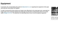
(Image: Connection between steel pipe and DH with the aid of a winch cable [Stein89g]) In principle, the corresponding discussion of Abschnitt 5.1.1.2 regarding the equipment of the pipe ramming with closed pipe front applies. In order to transmit the short-stroke ram impact more effectively to the steel pipe point, especially for longer pipes, the connection between the steel pipe and the DH is enhanced by means of a winch cable (Bild 5.1.2.2). The … |
|
The pipe ramming with closed pipe front can be used for jacking steel pipes with an external diameter ≤ 150 mm in displaceable soils [ATVA125:1996] of soil class L to DIN 18319 [DIN18319:2000]. In comparison to the DH as a solo apparatus, the area of application is extended to artificially filled or unstable soils such as quick sands, loam soils or soils with groundwater as the reaction force here does not have to be absorbed by the jacket friction … |
|
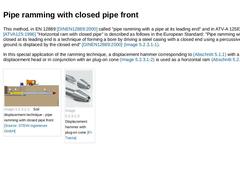
This method, in EN 12889 [DINEN12889:2000] called "pipe ramming with a pipe at its leading end" and in ATV-A 125E [ATVA125:1996] "Horizontal ram with closed pipe" is described as follows in the European Standard: "Pipe ramming with a pipe closed at its leading end is a technique of forming a bore by driving a steel casing with a closed end using a percussive hammer. The ground is displaced by the closed end" [DINEN12889:2000] (Bild 5.1.2). In this … |
|
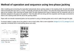
After installing and connecting the (typically) hydraulically driven jacking station in the starting shaft, the pilot drill string, consisting of interconnected drill rods each 1 m long, is statically pressed into the subsoil. This pilot drill string determines the future position of the pipe to be installed. After reaching the target shaft, the pilot displacement head is replaced with an expander with an external diameter adapted to the pipe to … |
|
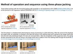
Three-phase jacking with the horizontal jacking with expander is not mentioned in EN 12889 [DINEN12889:2000]. A representative of this process is the Japanese method SPEEDER SR-12 [FI-Hosho] [FI-Speed] (Bild 5.1.3.2) (Bild 5.1.3.2). |
(Image: SPEEDER SR-12 method with the most important equipment [FI-Hosho])
|
(Image: SPEEDER SR-12 method with the most important equipment [FI-Hosho])
|
The first phase is a displacement pilot boring by means of pressing … |
|
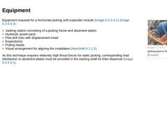
(Image: Horizontal jacking plant in the starting shaft [FI-Lanci]) Equipment required for a horizontal jacking with expander include (Bild 5.1.3.2) (Bild 5.1.3.2) : - Jacking station consisting of a jacking frame and abutment plates
- Hydraulic power pack
- Pilot drill rods with displacement head
- Expander(s)
- Pulling heads
- Visual arrangement for aligning the installation (Abschnitt 5.1.1.2).
As this technique requires relatively high thrust forces for static … |