|
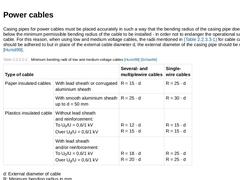
Casing pipes for power cables must be placed accurately in such a way that the bending radius of the casing pipe does not fall below the minimum permissible bending radius of the cable to be installed - in order not to endanger the operational safety of the cable. For this reason, when using low and medium voltage cables, the radii mentioned in Tabelle 2.1.2.2 for cable casing pipes, should be adhered to but in place of the external cable diameter … |
|
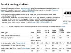
(Image: Pulling in a DHC with skids in a casing pipe [FI-Brugg]) Flexible district heating pipelines (Abschnitt 1.1.3), especially so-called district heating cables (DHC), are usually placed in a casing pipe (Abschnitt 2.2). Besides the aspects mentioned in Abschnitt 2.1.2, the following must also be considered [FI-Brugg] : - The maximum casing pipe length must not be longer than the 30 m maximum length of the standard types of DHC.
- The pulling in of …
|
|
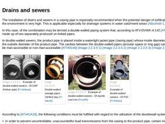
The installation of drains and sewers in a casing pipe is especially recommended when the potential danger of exfiltrating sewage to the environment is very high. This is applicable especially for drainage systems in water catchment areas (Abschnitt 1.1.4.1). In this case, of the combination may be termed a double-walled piping system that, according to ATV-DVWK-A 142 [ATVA142d] is made up of two separately produced un-linked pipes. In double-walled … |
|
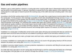
Whether a gas or water pipeline is placed in a casing pipe when crossing traffic lanes is determined mostly by the materials used and the joints of the product pipes. In general, importance is placed first on the safety aspects of the respective case; for instance, a casing pipe for a water pipe is meant to prevent the washing away of the traffic lanes due to leaking water in the case of a pipe fracture. According to the DVGW working sheet W 305 [… |
|
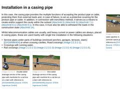
(Image: Installing a water pipeline in a casing pipe (annular space grouted) with reference to [DVGWAGW307] [Image: S&P GmbH]) In this case, the casing pipe provides the multiple functions of accepting the product pipe or cable, protecting them from external loads and, in case of failure, to act as a protective covering for the product pipe or cable. In addition, in connection with trenchless method, it serves as a means to create and/or support the … |
|
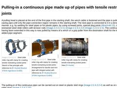
A pulling head is placed at the end of the first pipe in the starting shaft, the winch cable is fastened and the pipe is pulled into the casing pipe until only the pipe connection region remains in the starting shaft. The next pipe is connected to it in a tensile restrained manner, e.g. by welding for steel pipes or for plastic pipes, by using screwed joints, special plug joints (Abschnitt 13), or tensile restrained steel slide rollers with tension … |
|
|
|
|
|
|
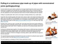
(Image: Pipe pulling equipment (WIMAG) [FI-WIMAG] - With cross piece) |
|
(Image: Pipe pulling equipment (WIMAG) [FI-WIMAG] - With round grab) |
For this method, the winch cable is pulled from the target shaft through the product pipe and the pulling force is applied to the last pipe still in the starting shaft by means of a pressure plate or cross piece situated at the rear end of the already jointed continuous pipe. In this way, the pipes are only … |
|
In this insertion method, the pipes are pulled into the casing pipe individually and connected to each other at site. The fixing of the pipe string in position is carried out by fastening the first pipe in the target shaft. (Video: Discrete pipe process - Pulling-in of single pipes into the section) For pulling in pipes, use can be made, for instance of inflatable packers or a special pulling-in body onto which the pipe is pushed and whose end is provided … |

|
|
|
In the pushing-in process, the individual pipes or pipe section are connected in the starting shaft and the lengthened pipe string is pushed in by the length of the added pipe(s). (Video: Pushing-in of discrete pipes by means of a hydraulic cylinder wired inside the neighbouring sewer - Principle sketch) The simplest method is by pushing in the pipe by hand using simple aids. This process, however, can only be used to a limited extent for: |
|
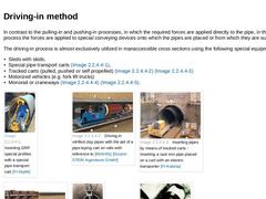
In contrast to the pulling-in and pushing-in processes, in which the required forces are applied directly to the pipe, in the drive process the forces are applied to special conveying devices onto which the pipes are placed or from which they are suspended. The driving-in process is almost exclusively utilized in manaccessible cross sections using the following special equipment: - Sleds with skids,
- Special pipe transport carts (Bild 2.1.3.3),
- Tracked …
|
|
When undertaking the later insertion of product pipes into casing pipes previously installed using a trenchless method (Abschnitt 2.1.2), the type of installation varies depending on the loading of the individual pipes or pipeline caused by the installation as follows [Stein83c] : - Pulling-in method
- Pulling-in a continuous pipe made up of pipes with tensile restrained joints;
- Pulling-in a continuous pipe made up of pipes with non-restrained joints (…
|
|
Grouting the annular space between the directly installed casing pipe or host pipe and a later installed product pipe can be beneficial depending on the local situation and application (e.g. crossing of steel gas and water pipes and pipes of ductile cast iron under traffic installations such as rail lines, roads and waterways [DVGWAGW307]). Grouting the annular space can achieve the following for the product pipe: - Positional security;
- Providing a …
|

|
In the following, single installations will be understood to be the separate installation of individual lines in a prepared line and gradient (e.g. in the road cross section to DIN 1998 [DIN1998] (Abschnitt 1.2)). Such installations can be carried out by means of (Bild 2) - Direct installation,
- Installation in a casing pipe.
|
|
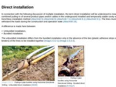
In connection with the following discussion of multiple installation, the term direct installation will be understood to mean the direct combined pulling-in of several product pipes and/or cables in the underground installed and temporarily stable cavity with the aid of a trenchless installation method (Abschnitt 5) (Abschnitt 6) (Abschnitt 7.1) (Abschnitt 8.1) (Abschnitt 9.1). The lines must be able to withstand the loads during the construction … |
|
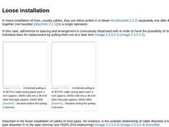
In loose installation of lines, usually cables, they are either pulled in or blown in (Abschnitt 2.1.2) separately one after the other or together (not bundled (Abschnitt 2.2.1)) in a single operation. In this case, adherence to spacing and arrangement is consciously dispensed with in order to have the possibility of removing individual lines for replacement by pulling them out at a later time (Bild 2.2.2.1) (Bild 2.2.2.1). | (Image: Combined pulling-… |
|
|
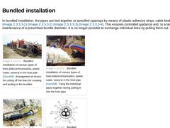
In bundled installation, the pipes are tied together at specified spacings by means of plastic adhesive strips, cable binders or skids (Bild 2.2.2.2) (Bild 2.2.2.2) (Bild 2.2.2.2) (Bild 2.2.2.2). This ensures controlled guidance and, to a large extent, the maintenance of a prescribed bundle diameter. It is no longer possible to exchange individual lines by pulling them out. | (Image: Bundled installation of various types of lines (telecommunication, … |
|
|
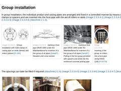
In group installation, the individual product and casing pipes are arranged and fixed in a controlled manner by means of multiple clamps or spacers and are inserted into the host pipe with the aid of rollers or skids (Bild 2.2.2.3) (Bild 2.2.2.3) (Bild 2.2.2.3) (Bild 2.2.2.3) (Abschnitt 2.1.3). | (Image: Group installation with multi-clamps in casing pipe on skids (below) and rollers (above) [FI-DSI]) | (Image: Jacking a host pipe DN/ID 1000 under the … |
|
|
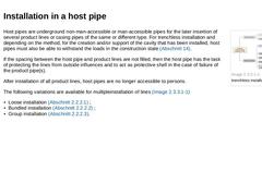
(Image: Variations of the trenchless installation of lines) Host pipes are underground non-man-accessible or man-accessible pipes for the later insertion of several product lines or casing pipes of the same or different type. For trenchless installation and depending on the method, for the creation and/or support of the cavity that has been installed, host pipes must also be able to withstand the loads in the construction state (Abschnitt 14). If the … |
|
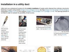
Utility ducts are underground systems for the orderly installation of supply and/or disposal lines utilizing a structural shell for line fastening or support using dowels (Bild 2.2.3) (Bild 2.2.3), clip rings (Bild 2.2.3) (Bild 2.2.3) (Bild 2.2.3), multiclamps (Bild 2.2.2.3) or line supports (Bild 2.2.3) (Bild 2.2.3) (Bild 2.2.3). The spacings between the lines are not filled in order to maintain the possibility of later access. |
|
A man-accessible utility tunnel, also called utility corridor or utilidor, is an enclosed corridor-like structure for the accessible installation of supply and/or disposal lines consisting of utility tunnel path as well as access, erection, ventilating, branch and joining structures [Stein02] [Stein94a] [Stein97d] [Stein98e]. Besides the functions of the utility duct (Abschnitt 2.2.3), the man-accessible utility tunnel as a geometrically restricted … |
|
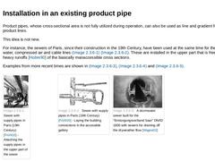
Product pipes, whose cross-sectional area is not fully utilized during operation, can also be used as line and gradient for other product lines. This idea is not new. For instance, the sewers of Paris, since their construction in the 19th Century, have been used at the same time for the installation of water, compressed air and cable lines (Bild 2.2.5) (Bild 2.2.5). These are installed in the upper part that is free even during heavy runoffs [Hobre90] … |
|
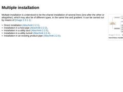
(Image: Variations of the trenchless installation of lines) Multiple installation is understood to be the shared installation of several lines (one after the other or altogether), which may also be of different types, in the same line and gradient. It can be carried out by means of (Bild 2.2) : - Direct installation (Abschnitt 2.2.1),
- Installation in a host pipe (Abschnitt 2.2.2),
- Installation in a utility duct (Abschnitt 2.2.3),
- Installation in a utility …
|
|
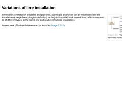
(Image: Variations of the trenchless installation of lines) In trenchless installation of cables and pipelines, a principal distinction can be made between the installation of single lines (single installation), or the joint installation of several lines, which may also be of different types, in the same line and gradient (multiple installation). An overview of further divisions can be found in Bild 2. |
|
The term "Trenchless Technology for Installation of Cables and Pipelines by Jacking or Drilling" (referred to hereareafter as trenchless installation), is understood to mean "The Underground installation of lines by means of pulling in, pushing in, pressing in or ramming in into a cavity (borehole) made in the soil by means of boring or drilling." Influenced by DIN 20301 [DIN20301], boring or drilling is designated as the mechanised creation of a … |