|
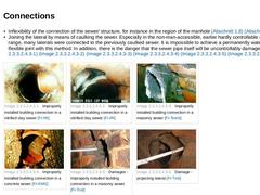
- Inflexibility of the connection of the sewer/ structure, for instance in the region of the manhole (Abschnitt 1.8) (Abschnitt 2.4.1).
- Joining the lateral by means of caulking the sewer. Especially in the non-man-accessible, earlier hardly controllable nominal size range, many laterals were connected to the previously caulked sewer. It is impossible to achieve a permanently watertight and flexible joint with this method. In addition, there is the …
|

|
The main cause of leaks is the result of construction work that is not carried out in accordance with the recognised rules of the technology. Thus, in many cases for instance, the sewers often had to undertake the additional duties of a land drainage pipe. Among others, this was achieved by using pipes with half sockets (Bild 2.2.2.1.3) (Bild 2.2.2.1.3) (Bild 2.2.2.1.3) in which the gasket in the region of the crown was also purposely dispensed with. |
|
During operation, unplanned stresses can be applied to the pipe joints or components from the outside as well as from the inside and these can lead to damage with leaks, e.g. - Root ingress (Abschnitt 2.3.2.3).
- Temperature influences.
- Exceeding the permissible highest temperatures of the sewage to DIN 19550 [DIN19550], DIN 1986 Part 1 [DIN1986-1:1978] or DIN 19543 [DIN19543:1982] :
up to DN 350: 45° C,
from DN 400: 35° C.
At an ambient temperature …
|
|
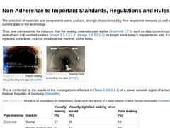
The selection of materials and components were, and are, strongly characterised by their respective stresses as well as by the current state of the technology. Thus, one can assume, for instance, that the sealing materials used earlier (Abschnitt 1.7.1) such as clay, cement mortar, poured asphalt and cold-worked sealers (Bild 2.2.2.1) (Bild 2.2.2.1) no longer meet today's requirements and, if not already replaced, contribute, in a not unsubstantial … |

|
Leakiness can also occur as a result of other damage such as: - Positional deviation (Abschnitt 2.4.1) ;
- Mechanical wear (Abschnitt 2.5) ;
- Corrosion (Abschnitt 2.6.1) ;
- Deformation (Abschnitt 2.7.1) ;
- Cracks, pipe break, collapse (Abschnitt 2.8) ;
The causes of this type of damage will be dealt with in more detail in the appropriate sections. |
|
There are numerous causes for the occurrence of leaks and they can be arranged in the following groups [ATVM143-1:1989] : - Non-adherence with EN 1610 [DINEN1610:1997], DIN 19550 [DIN19550], prEN 12889 [DINEN12889:1997], material standards or regulations and guidelines for
- Planning,
- Material and component selection,
- Workmanship,
- Operation;
- Material ageing;
- As a result of other damage.
|
|
In professional circles the theory was long maintained that seepage of the sewage could not occur because leaks block or seal themselves due to the solids in the sewage [Stein88g]. Another theory is that the exfiltration of sewage from leaking sewers is a desirable and environmentally friendly component of wastewater disposal. The reasoning behind this points to the earlier usual targeted seepage of a portion of the communal sewage and the almost … |

|
If leaking gravity flow sewers or structures of drain and sewer systems are constantly or occasionally in the groundwater (Bild 2.2.3.1), then groundwater infiltration will occur (Bild 2.2.1) (Bild 2.2.1) whereby, at the same time, soil material from the embedment can be flushed in.
Infiltrating water belongs to the category of extraneous water and is thus an unwanted portion of the wastewater to be discharged [ATV82] [Graf84] [Klass85] [Liers85]. |
|
The primary consequences of damage caused by leaks in sewers as well as to structures of drain and sewer systems are: - The exiting of sewage (exfiltration); and
- The ingress of groundwater (infiltration) and soil.
In both cases they always form the starting point for possible consequential damage [Horne85] [Young84]. |

|
|
|
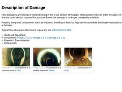
Flow obstacles are objects or materials lying in the cross section of the pipe, which project into it or cross through it in such a manner that the cross section required for a proper flow of the sewage is no longer completely available. Properly integrated components such as reducers, throttling or back-up flaps do not constitute discharge obstructions in the sense of a damage. Typical flow obstacles often found in practice are [ATVM143-1:1989] : |
|
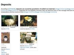
According to [DIN4046], deposits are caused by gravitation of settled out materials (Bild 2.3.2.1) (Bild 2.3.2.1) (Bild 2.3.2.1) (Bild 2.3.2.1). If deposits are not regularly removed, they can become more or less strongly fixed due to their compositions and the course of time (Bild 2.3.2.1) (Bild 2.3.2.1) (Bild 2.3.2.1). | (Image: Hardened deposits [FI-IfK]) | (Image: Sewer blockage caused by deposits [FI-KMG]) | | (Image: Hardened deposits - Sewer filled … |
|
|
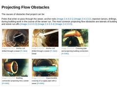
The causes of obstacles that project can be: Poles that enter or pass through the sewer, anchor rods (Bild 2.3.2.2) (Bild 2.3.2.2), injection lances, drillings, among others during building work in the course of the sewer run. The most common projecting flow obstacles are laterals of buildings, properties and street run-offs (Bild 2.3.2.2) (Bild 2.3.2.2) (Bild 2.3.2.2). |
(Image: Anchor rod drilled through a sewer [FI-Jtele])
|
(Image: Anchor rod drilled … |
|
|
|
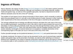
(Image: Root ingress in the region of a pipe joint [FI-KMG])
|
|
(Image: Root ingress in the region of a pipe joint [FI-IfK])
|
Next to deposits, the ingress of roots (Bild 2.3.2.3) (Bild 2.3.2.3) into sewer systems presents a further common form of flow obstacles, although root resistance of all piping materials, sealing media and gasket rings, as well as of the complete pipe joints, has been a requirement of all the effective standards since the … |
|
According to [ATVM143-1:1989], the following are the causes of damage from flow obstacles: - Non-adherence to the standards and regulations such as EN 1610 [DINEN1610:1997], prEN 12889 [DINEN12889:1997], ATV-A 115E [ATVA115b] ;
- Incorrect planning (e.g. pipe gradients);
- Incorrect construction work;
- Insufficient cleaning;
- Introduction of depositing and/or materials capable of binding;
- Pipe gaskets or pipe joints that are not root resistant;
- Influences …
|
|
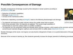
(Image: Sewer blockage caused by deposits [FI-KMG]) Possible consequences of damage caused by flow obstacles in sewer systems according to [ATVM143-1:1989] are: - Reduction of hydraulic capabilities;
- Blockage (Bild 2.3.3) ;
- Increase of the maintenance effort.
Furthermore, depositing, according to [Rüttg87], leads to the following disadvantages and damage: - The deposits and backed up water volumes reduce the usable sewer back up space.
- With strong rainwater …
|

|
|
|
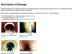
Positional deviation is understood to be the unplanned deviation of sewers and structures from a nominal position determined by planning and/or by the situation during construction. With sewers, one differentiates the positional deviation according to [ATVM143-1:1989] between: - Vertical direction (e.g. displacement) (Bild 2.4.1) ;
- Horizontal direction (Bild 2.4.1) ;
- Longitudinal direction (Bild 2.4.1) (Bild 2.4.1).
|
(Image: Positional deviation in the … |
|
|
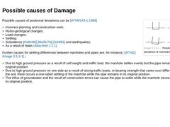
(Image: Possible positional deviations of manholes) Possible causes of positional deviations can be [ATVM143-1:1989] - Incorrect planning and construction work;
- Hydro-geological changes;
- Load changes;
- Settling;
- Subsidence [Hollm85] [Meißn76] [Schil81] and earthquakes;
- As a result of leaks (Abschnitt 2.2.1).
Further causes for settling differences between manholes and pipes are, for instance, [ATV82] (Bild 2.4.2) : - Due to high ground pressure as a result …
|
|
The consequences of positional deviations on the sewers depends on the type of pipe - pressure pipe or gravity flow pipe - and on the pipe-soil-system - inflexible or flexible - or on the type of pipe joint - rigid, tensile stiff or flexible. The most common causes of damage resulting from movement associated with positional deviations and depending on its extent are [ATVM143-1:1989] : - Breaking off of the connecting pipes;
- Loss of functionality due …
|

|
|
|
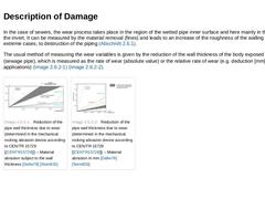
In the case of sewers, the wear process takes place in the region of the wetted pipe inner surface and here mainly in the region of the invert. It can be measured by the material removal (fines) and leads to an increase of the roughness of the walling and, in extreme cases, to destruction of the piping (Abschnitt 2.6.1). The usual method of measuring the wear variables is given by the reduction of the wall thickness of the body exposed to the wear (… |
|
During the conveyance of water - solids mixtures as is usual in sewers, wear is caused primarily by various materials carried along by the water, such as sand, gravel, solid metal parts, textiles, etc. In the present application this is dependent on [Järve93] : - Piping materials (Bild 2.5.1) (Bild 2.5.1) ;
- Pipe diameter;
- Stressing or expansion condition of the pipe materials;
- Density of the water - solids mixture;
- Composition of the water - solids mixture;
|
|
In sewage channels, stresses can arise during operation, which result in drip erosion in the region of the building connections due to the impact of incoming sewage on the sewer wall opposite the connection and in drop installations. Damage due to this type of stressing is not yet known. |
|
When a flow of water at a high velocity is parallel to a border surface, then every geometric change in this surface has a resultant on the flow and causes local regions of lower pressure. When the static reduced pressure of the flowing water then falls below the vapour pressure, water vapour bubbles are formed. If these occur in regions in which the static pressure again lies above the vapour pressure - this is mostly shortly behind the position … |