
|
Jacking pipes are to be delivered packed and are to be stored on the construction site in such way that they are secured against rolling and sliding also in the case of individual withdrawal [ATVA125:1996] [BGI780]. Excessive stacking heights should be avoided so that pipes in the lower part of the stacks are not overloaded. Stacks of pipes shall not be placed close to open trenches or shafts. Pipes with protective coatings shall not be stored where … |
|
|
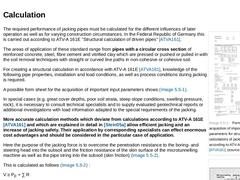
(Image: Form sheet for the acquisition of important input parameters for structural calculations of jacking pipes according to ATV-A 161E [ATVA161] (source: [FI-RG]))
|
|
(Image: Penetration resistance and skin friction [Stein05a])
|
|
(Image: Surface deformation in dependence on the support pressure or face resistance with reference to [ISEKI])
|
|
(Image: Surface deformation in dependence on the support pressure or face resistance with reference to [… |
|

|
In the following, jacking pipes will be understood to be prefabricated pipes with the following characteristics: pipes with non-restrained, flexible joints within the wall thickness; pipes have smooth even external contours; these pipes are pressed-in or pushed-in into the subsoil or cavity [Stein05a]. |
|
The results of the geotechnical investigation as well as the laboratory analyses must be determined accurately by the geotechnical specialist or engineering geologist and described in a geotechnical report. According to DIN 4020 [DIN4020:2003] [DIN4020:2003], the geotechnical report comprises the presentation and evaluation of the results of all geotechnical investigations and the conclusions to be drawn with regard to the project and the construction … |

|
(Image: Diagram of soil and rock classification in accordance with DIN 18319 [DIN18319]) The soil and rock classes, for trenchless technology for installation of prefabricated pipes of any profile by means of pressing-in, pushing-in, ramming-in or pulling-in, is defined in the Federal Republic of Germany by DIN 18319 " Contract procedures for building works - Part C: General technical specifications for building works; Pipe drilling works " [DIN18319:… |

|
When using the trenchless method of construction a sufficient and carefully carried out geotechnical investigation is decisive for the technical and economic success of a trenchlessly carried out sewer construction measure since the geotechnical and hydrogeological subsoil conditions decisively determine the selection of the jacking technique (machine type, conveying system, cutting head variant). In the sense of DIN 4020 [DIN4020:2003] [DIN4020:2003], … |
|
Shafts are usually always necessary for trenchless installation of pipelines with the methods of microtunnelling and pilot pipe jacking. The term shaft is understood to be a depression in the ground surface that is created by sinking (excavation or vertical boring), with suitable support, that serves for the underground creation of bore holes with the aid of the methods of trenchless installation and for the transport of humans, machines, substances (… |
|
|
(Image: Utilisation of a shaft for several jackings [Stein05a])
|
|
(Image: Shaft coverings during building pauses - Rectangular shaft covering [Stein05a])
|
|
(Image: Shaft coverings during building pauses - Circular shaft covering [FI-KCMM])
|
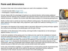
The location and the number of shafts are decisively influenced by the lay out of the sewer and the requirements of the trenchless construction method (e.g. realisable jacking length (Abschnitt 4.4), straight … |
|
|
(Image: Examples of cross sectional shapes of starting shafts in microtunnelling [FI-Herreb] - Circular (open sinking shaft), jacking cylinder arranged parallel to the jacking pipe/to the microtunnelling machine)
|
|
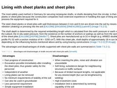
(Image: Shaft support based on sheet planks or sheet piles - View into a rectangular starting shaft secured with sheet piles and several waling and brace layers (jacking pipe arranged in front of the pressure ring) [FI-Herreb])
|
|
(Image: … |
|
|
The most widely used method in Germany for securing rectangular shafts, or shafts deviating from the circular, is that of using sheet planks or sheet piles because the construction companies have extensive experience in handling this type of lining and usually also possess the equipment required for it. The steel sheet planks or sheet piles with wall thicknesses between 3 mm and 8 mm are driven into the soil by means of ramming, vibration (shaking) … |
|
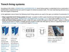
According to EN 13331-1 [DINEN13331-1a] [DINEN13331-2], trench lining system is understood to be a construction of prefabricated components that are used for support of vertical excavation walls. The main load-bearing elements are panels, slide rails and support components. In the application case at hand, the following trench lining systems are used in the open cut method of construction [DINEN13331] : - Edge-supported trench lining system (ES type): "…
|
|
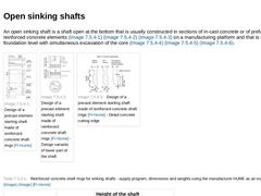
An open sinking shaft is a shaft open at the bottom that is usually constructed in sections of in-cast concrete or of prefabricated reinforced concrete elements (Bild 6.4.3) (Bild 6.4.3) (Bild 6.4.3) on a manufacturing platform and that is sunk to its foundation level with simultaneous excavation of the core (Bild 3) (Bild 3) (Bild 3). | (Image: Design of a precast element starting shaft made of reinforced concrete shaft rings [FI-Hume]) |
(Image: Design … |
|

|
(Image: Methods for securing shafts [Stein05a]) Decisive for the selection of a method of shaft construction, i.e. the measures for sinking and securing of a shaft, can be, for example [Stein05a] : - Dimensions (length, width and depth of the shaft)
- Selected jacking method
- Geological and hydrogeological conditions
- Local conditions (e.g. available space, surface utilization, traffic loads)
- Environmental protection (limiting values of emissions during …
|
|
When opening up the exit and entrance openings with jacking in soil that is free of groundwater, the main task is to avoid ground failure. In the cases in which a bentonite suspension is injected into the annular gap for reducing skin friction, or in which, despite the absence of groundwater, closed shields with fluid support or earth pressure support of the working face are used, care must be taken regarding sealing measures like in saturated subsoils (… |
|
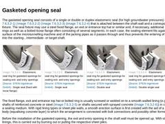
The gasketed opening seal consists of a single or double or duplex elastomeric seal (for high groundwater pressures) (Bild 6.5.2.1) (Bild 6.5.2.1) (Bild 6.5.2.1) (Bild 6.5.2.1) that is attached between the shaft wall and a correspondingly seal fixture. The seal fixture may use a steel fixed flange, an exit or entrance top hat or similar and, if necessary, additional intermediate rings as well as a bolted loose flange often consisting of several segments. … |
|
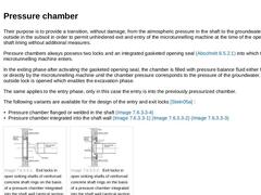
Their purpose is to provide a transition, without damage, from the atmospheric pressure in the shaft to the groundwater pressure outside in the subsoil in order to permit unhindered exit and entry of the microtunnelling machine at the time of the opening of the shaft lining without additional measures. Pressure chambers always possess two locks and an integrated gasketed opening seal (Abschnitt 6.5.2.1) into which the microtunnelling machine enters. |
|
(Image: Dewatering properties of different types of soils with water retention measures [Herth95]) The following measures are possible in order to prevent ground failure and groundwater inflows when creating and traversing the exit and entry openings [Stein05a] : - Open water retention
- Groundwater lowering
- Groundwater cut-off
The simplest solutions, when technically possible are water retention measures for lowering the groundwater level [Rappe96] [DIN18305]. |

|
Within the scope of microtunnelling and pilot pipe jacking a difference is made between the following phases of jacking [Konra01] : - Exiting (starting)
Exiting is the phase of jacking from the beginning of opening the lining or the start of the approach of the boring head to the in-situ subsoil up to the completion of all special measures. The sequence of the activities can be repeated when traversing an intermediate shaft.
- Excavation
Excavation is the …
|
|
Shafts for drains and sewers consisting of jacking pipes have to correspond to EN 476 [DINEN476:1997] and ATVDVWK A 157E [ATVA157], respectively to the materialrelating shaft standards based on them (e.g. EN 1917 [DINEN1917:2004] and DIN V 4034-1 [Konra01] for shafts of precast concrete- and reinforced concrete elements). A manhole (DN/ID 1000) is usually built into the starting- or target shaft (double shell construction method, respectively shaft-… |
|
|
|
|
(Image: Obstacles - Boulders removed via an auxiliary pit [Hambu85b])
|
|
(Image: Obstacles - Boulder bored into by a microtunnelling machine (external diameter 410 mm) [FI-Steinb])
|
The term obstacle in trenchless installation must be viewed from a contractual [Liepe02] as well as a technical point of view. From a technical aspect, one differentiates between: - Non-removable obstacles
- Removable obstacles
Non-removable obstacles in trenchless installation … |
|
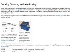
In the steerable methods of microtunnelling and pilot pipe jacking the whole pipe string in the form of a linked chain behind the microtunnelling machine (Bild 8) or the flexible drill rod string must follow the pilot boring head. Thus the bore path must necessarily also be the line and gradient of the final sewer. This means that all deviations from the design position remain almost unchanged as errors. The jacking steering has to ensure that the … |
|
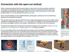
(Image: Creation of the core bore by means of a core drilling machine rectangular and central to the axis of the sewer [FI-DS]) When connecting a lateral which has been laid in a line trench or by the trenchless method of construction by employing the open-cut method the section concerned of the sewer has to be excavated and secured by observing EN 1610 [DINEN1610:1997] [DINEN1610-1:1997], ATV-DVWKA 139E [ATVA139a] and DIN 4124 [DIN4124:2002]. Since … |
|
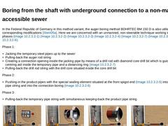
In the Federal Republic of Germany in this method variant, the auger boring method BOHRTEC BM 150 D is also utilised with corresponding modifications [Stein05a]. Here we are concerned with an unmanned, non-steerable technique working in three-phases (Bild 9.1.2.1) (Bild 9.1.2.1) (Bild 9.1.2.1) (Bild 9.1.2.1) (Bild 9.1.2.1) (Bild 9.1.2.1) (Bild 9.1.2.1). Phase 1: - Jacking the temporary steel pipes up to the sewer
- Pulling-back the auger rod string
- Creating …
|
|
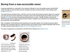
(Image: Boring a lateral from a man-accessible sewer (BOHRTEC BM 150 DT method)) In special applications, especially in the making of laterals to man-accessible sewers (≥ DN/ID 1200), the pipe as well as other secured cavaties can take over the function of the starting shaft (Bild 9.1.2.2). The auger boring machine that is used here can be moved into the pipe string by means of a special cart and can be set at the respective connection point to the … |