|
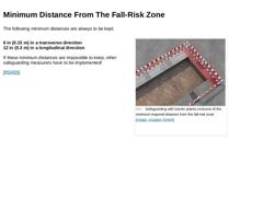
The following minimum distances are always to be kept: 6 in (0.15 m) in a transverse direction
12 in (0.3 m) in a longitudinal direction If these minimum distances are impossible to keep, other safeguarding measurers have to be implemented! [RSA95] (Image: Safeguarding with barrier planks inclusive of the minimum required distance from the fall-risk zone) |

|
For reasons of safety, excavations and trenches with sloping walls, as well as sloped edges, are only to be accessed after the stability of the earth or rock walls is ensured. This also holds true for excavations and trenched yet to be lined, for as long as the respective shoring has not been inserted [DIN4124:2002]. |
|
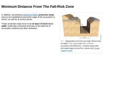
In addition, according to [DIN4124:2002], protective strips have to be established around the edge of the excavation or trench, as well as at access points. These protective strips have to be at least 2 ft (0.61 m) in width, preferably horizontal and have to be kept free of excavation material and other obstacles. (Image: Safeguarding of trenches and shafts without lining for depths > 4 ft / 1.25 m and ≤ 6 ft / 1.75 m in accordance with [DIN4124c] – … |

|
|

|
Animation: Exercise Work safety - Minimum working distance [Animation: visaplan GmbH]. This interactive object is only visible in the online version of the module. |

|
Animation: Exercise Work safety - Excavator – Danger zone [Animation: visaplan GmbH]. This interactive object is only visible in the online version of the module. |

|
Animation: Exercise Work safety - Traffic control [Animation: visaplan GmbH]. This interactive object is only visible in the online version of the module. |

|
Congratulations! You have successfully finished this lesson. Next you will have the opportunity to review the newly acquired knowledge with an interactive questionnaire. You can of course still navigate back to any point in the lessons if you wish to review a specific point or subject. Stay curious! |
|
The aspects of occupational health and safety that must be taken into account in the context of civil engineering work, especially in the construction of pipelines and sewers using the open cut method, are very diverse. They harbor a considerable potential for danger for those working on the construction site, but also for uninvolved persons. After completing this module, you will have knowledge regarding: - risks and hazardous areas;
- securing construction sites in traffic areas;
- tools and equipment for safe working.
|

|
Publication with friendly permission of the MUNLV NRW, Düsseldorf, Germany. Imprint Editor
Prof. Dr.-Ing. Stein & Partner GmbH
Konrad-Zuse-Str. 6
D-44801 Bochum
Phone: 0049-234-5167-0
Fax: 0049-234-5167-119
office@stein.de
www.stein.de Compilation and Editing
University-Professor Dietrich Stein
Ansgar Brauer Picture Editors
visaplan GmbH, Bochum
Prof. Dr.-Ing. Stein & Partner GmbH, Bochum This guideline was originally published in German by the Ministry for Environment … |
|
(Image: Dr.-Ing. Robert Stein) To the proper development of new construction areas also belongs the sewage disposal, of course. Also in the future it will remain necessary to build sewers new within the scope of site development. When rehabilitating sewers, which will be one of the main tasks of the local authorities, municipalities or sewer operators in the future, to an increasing degree a new line is chosen in dependence on its load and its condition, … |
|
|
(Image: Disadvantages of the open cut method for installing drains and sewers (Part 1) [GSTT])
|
|
(Image: Disadvantages of the open cut method for installing drains and sewers (Part 2) [GSTT])
|
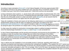
According to latest estimations [Dohma97], in the Federal Republic of Germany approximately 2000 km of sewers will have to be newly installed each year until 2015 with an investment volume of over 1.2 billion € per year. Over 80% of these sewers are < DN/ID … |

|
For planning, draft, call for tenders, construction preparation, realisation, final acceptance and billing of construction measures for the new installation of sewers by means of trenchless installation, all EN standards and regulations by the DWA (German Association for Water, Wastewater and Waste e.V., since November 2004 called ATV or ATV-DVWK), which are valid in the Federal Republic of Germany for the planning and construction of drain and sewer … |
|
|
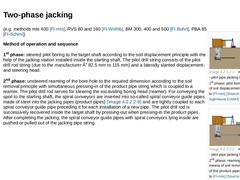
(Image: mts 400 method - pilot pipe jacking in two phases - 1st phase: pilot boring by means of soil displacement with reference to [FI-mts] [Image: S&P GmbH])
|
|
(Image: mts 400 method - pilot pipe jacking in two phases - 2nd phase: reaming boring by means of soil removal and jacking of the product pipes with reference to [FI-mts] [Image: S&P GmbH])
|
(e.g. methods mts 400 [FI-mts], RVS 80 and 160 [FI-Wirthb], BM 300, 400 and 500 [FI-Bohrt], PBA … |
|
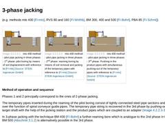
(e.g. methods mts 400 [FI-mts], RVS 80 and 160 [FI-Wirthb], BM 300, 400 and 500 [FI-Bohrt], PBA 85 [FI-Schmi]) |
(Image: mts 400 method - pilot pipe jacking in three phases - 1st phase: pilot boring by means of soil displacement with reference to [FI-mts] [Image: S&P GmbH])
|
(Image: mts 400 method - pilot pipe jacking in three phases - 2nd phase: reaming boring by means of soil removal and jacking of the temporary pipes with reference to [FI-mts] [… |
|
|
|
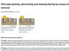
|
(e.g. method BM 500 [FI-Bohrt]) | (Image: 1st phase: pilot boring by means of soil removal with reference to [FI-Bohrt] [Image: S&P GmbH]) | (Image: 2nd phase: reaming boring and jacking of the product pipes with reference to [FI-Bohrt] [Image: S&P GmbH]) |
Method of operation and sequence 1st phase: steered pilot boring (bore hole diameter 419 mm) to the target shaft according to the soil removal principle with the help of a jacking station installed … |
|
In general the following techniques of unmanned, steerable pilot pipe jacking, in the literature also known as guided boring, are applied, whereas the jacking is always carried out in two (Abschnitt 3.1.1.1) (Abschnitt 3.1.2) or a maximum of three (Abschnitt 3.1.1.2) sequential phases: - Pilot boring, by means of soil displacement and reaming boring by means of soil removal
Two-phase jacking (Abschnitt 3.1.1.1)
Three-phase jacking (Abschnitt 3.1.1.2)…
|
|
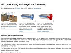
(e.g. methods mts 1000 [FI-mts], RVS 100 A and 250 A [FI-Wirthb]) |
(Image: Microtunnelling with auger spoil removal in single phase jacking)
|
(Image: Microtunnelling with auger spoil removal in single phase jacking - Variant: driving the cutting head with the spiral conveyor)
|
(Image: Microtunnelling with auger spoil removal in single phase jacking - Variant: direct driving of the cutting head and separately driven spiral conveyor)
|
Method of operation … |
|
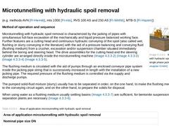
(e.g. methods AVN [FI-Herreb], mts 1000 [FI-mts], RVS 100 AS and 250 AS [FI-Wirthb], MTB-S [FI-Hazem]) (Image: Microtunnelling with hydraulic spoil removal in single phase jacking) Method of operation and sequence Microtunnelling with hydraulic spoil removal is characterized by the jacking of pipes with simultaneous full-face excavation of the mechanically and liquid pressure balanced working face. Further features are a cutting head and continuous … |

|
(e.g. methods AVP [FI-Herreb], MTB-P [FI-Hazem]) (Image: Microtunnelling with pneumatic spoil removal) Method of operation and sequence Microtunnelling with pneumatic spoil removal on the basis of a suction plant is characterized by the jacking of pipes with simultaneous full-surface excavation by a cutting head of the mechanically or earth-pressure balanced working face as well as by the continuous conveying of spoil out of the excavation chamber inside … |

|
The unmanned, steerable microtunnelling techniques employed base generally on the principle of soil removal. Depending on the way of conveying the spoil, it is differentiated between: - Microtunnelling with auger spoil removal (Abschnitt 3.2.1)
- Microtunnelling with hydraulic spoil removal (Abschnitt 3.2.2)
- Microtunnelling with pneumatic spoil removal (Abschnitt 3.2.3)
In all cases the different soil- and rock types are taken into account by the different … |
|
| (Image: Principle sketch of a jacking station for microtunnelling with auger spoil removal installed inside the starting shaft) | | (Image: Definition of the minimum clear dimensions for work space and traffic ways inside a jacking pipe string according to BGV C 22 §42 of the BG Bau with reference to [BGVC22] [Image: S&P GmbH] - Clear dimension profile in the form of a circular cross section) | | (Image: Definition of the minimum clear dimensions for … |
|
|
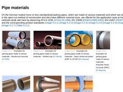
On the German market more or less standardized jacking pipes, which are made of various materials and which are also employed in the open-cut method of construction and also have different nominal sizes, are offered for the application case at hand and for the methods dealt with here by observing ATV-A 125E [ATVA125:1996], EN 12889 [DINEN12889:2000], EN 14457 [DINEN14457:2004] and the corresponding product standards (Bild 4.1) (Bild 4.1) (Bild 4.1) |
|
The connections of jacking pipes, called pipe joints or joints in the following, must ensure that the following criteria are met: - Tightness against internal and external pressure
- Transferral of longitudinal forces whilst ensuring lateral stability , as well as
- Corrosion protection of the pipe end faces (if applicable)
Examples of suitable pipe joints in the form of flexible, non-restrained socket and spigot joints according to EN 14457 [DINEN14457:… |