|
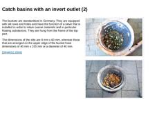
The buckets are standardised in Germany. They are equipped with slit rows and holes and have the function of a sieve that is installed in order to retain coarse materials and in particular floating substances. They are hung from the frame of the top part. The dimensions of the slits are 8 mm x 60 mm, whereas those that are arranged on the upper edge of the bucket have dimensions of 40 mm x 100 mm or a diameter of 40 mm. [DIN4052:2006] |
|
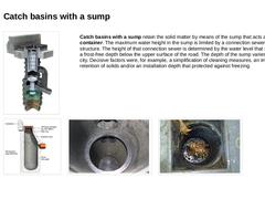
(Image: Separation catch basin) Catch basins with a sump retain the solid matter by means of the sump that acts as a settling container. The maximum water height in the sump is limited by a connection sewer in the main structure. The height of that connection sewer is determined by the water level that should be in a frost-free depth below the upper surface of the road. The depth of the sump varies from city to city. Decisive factors were, for example, … |
|
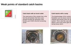
Catch basin with an invert outlet The weak point of this solution lies in the fact that all particles that have once passed through the openings of the bucket, go to 100% into the connecting sewer.
(Image: Catch basin with an invert outlet) Catch basins with a sump The disadvantage of this system is that floatables such as leaves cannot be retained and directly enter the sewer system. This is also the case with the debris in the … |
|
The distance between the catch basins depends on the amount of surface water, the intake capacity of their top parts and the gradient conditions of the street. The catchment area per catch basin should not exceed 500 m2 for rural roads and 400 m2 for urban roads. [RAS2005] Mostly, the catch basins are arranged at a distance of about 30 m apart in main roads and about 45 m in side roads (rural roads). Depending on their cross sectional shape, they are … |
|
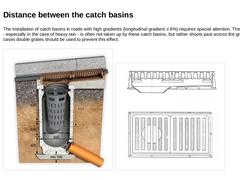
The installation of catch basins in roads with high gradients (longitudinal gradient ≥ 8%) requires special attention. The surface water - especially in the case of heavy rain - is often not taken up by these catch basins, but rather shoots past across the grate. In these cases double grates should be used to prevent this effect. (Image: Double grate according to ATV) (Image: Double grate - sectional and top view) |
|
|

|
For about 30 years now, people have been continually engaged in further developments of catch basins with the objective of improving both by means of technical and constructional changes. In recent years, the objectives were amended by the requirement to also use catch basins as local systems for the treatment of contaminated … |
|
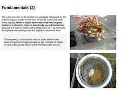
The solid retention in the bucket is essentially influenced by the entry of organic matter in the form of leaves, limbs and other bulky objects. When a catch basin does not hold organic matter in its bucket, there is practically no solid retention, because the mineral solids with particle sizes of < 16 mm pass through the slit openings with the slightest volumetric flow. Consequently, catch basins with an outlet at the invert level are generally inappropriate … |
|
Owing to this knowledge, many authors recommend, amongst others, the replacement of conventional catch basins by new structures with improved cleaning functions or solid retention. This improved separation of solids from the flow reduces operational requirements in by increasing cleaning intervals. [SteinR08] [Artie1988] [Sander1994] [Bromb1993] [Grott1991] [Giesl1997] [Kraut2000] [Stotz1998] [Somme2004a] [Somme2004] [Fraen2005] [Hilli2005] Such requirements … |
|
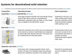
(Table: Composition, function and fields of application for different systems used for the decentralised solid retention) To see the images from the table in full view, please click on the images. |
|
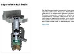
(Image: Separation catch basin) Out of all the catch basins introduced in the previous table, the separation catch basin is the only one that has been developed especially for the decentralised retention of settleable solids. Therefore, it is described in detail in the following section. Furthermore, the separation catch basin is also appropriate for the limitation of severe water pollution levels, because it interrupts the relevant input of particulate … |
|
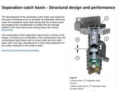
The development of the separation catch basin was based on the goal of retaining as far as possible all settleable solids that enter the separation catch basin along with the surface water and stopping the remobilisation of solids that are already settled in the catch basin even during heavy rain events [SteinR08]. The composition of the separation catch basin is shown in the image. It consists of a combination of the components from the conventional … |
|
|
|
Without doubt, the biggest problem of our sewer systems are the laterals or drain pipes of drain systems as well as the street run-offs and their connection to public sewers. Apart from individual exceptions that will be dealt with in detail later on, there was the request that “laterals should, as a rule discharge into the sewers outside of the manholes” (ATV-A 214) up until the introduction of DIN EN 1610 in 1997. [ATVA241a] [EN1610:2015] |
|
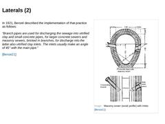
In 1921, Benzel described the implementation of that practice as follows: “Branch pipes are used for discharging the sewage into vitrified clay and small concrete pipes, for larger concrete sewers and masonry sewers, bricked in branches, for discharge into the latter also vitrified clay inlets. The inlets usually make an angle of 45° with the main pipe.” [Benze21] (Image: Masonry sewer (ovoid profile) with inlets [Benze21]) |
|
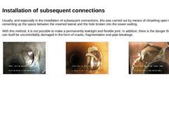
Usually, and especially in the installation of subsequent connections, this was carried out by means of chiselling open the sewer and cementing up the space between the inserted lateral and the hole broken into the sewer walling. With this method, it is not possible to make a permanently leaktight and flexible joint. In addition, there is the danger that the sewer can itself be uncontrollably damaged in the form of cracks, fragmentation and pipe breakage. |

|
In recognition of these facts for new sewer installations laterals are to be connected simultaneously with the construction of the sewer, whereby all connection types without branches are only permitted to be built by means of fittings and sealing elements which are standardised or have a valid test report. The inlet angle shall be 45°. For nominal sizes of the sewer ≥ DN 500 or a diameter ratio of about 1 : 3 between the connection- and sewer connections … |
|
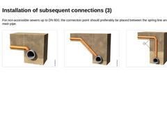
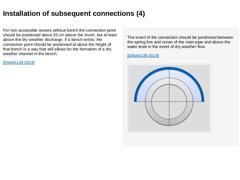
For non-accessible sewers up to DN 800, the connection point should preferably be placed between the spring line and crown of the main pipe. (Image: Examples of the jointing of connecting drains into the street sewer with reference to [ATVA139b] - Angled connection with small height difference [Image: S&P GmbH]) (Image: Examples of the jointing of connecting drains into the street sewer with reference to [ATVA139b] - Angled connection with small height … |
|
For non-accessible sewers without bench the connection point should be positioned about 35 cm above the invert, but at least above the dry weather discharge. If a bench exists, the connection point should be positioned at about the height of that bench in a way that still allows for the formation of a dry weather channel in the bench. [DWAA139:2019] The invert of the connection should be positioned between the spring line and crown of the main pipe … |
|
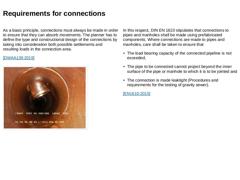
As a basic principle, connections must always be made in order to ensure that they can absorb movements. The planner has to define the type and constructional design of the connections by taking into consideration both possible settlements and resulting loads in the connection area. [DWAA139:2019] (Image: Faulty connection - lateral connection projects beyond the inner surface of the existing pipe) In this respect, DIN EN 1610 stipulates that connections … |

|
DIN EN 1610 provides the following connection variants: -
Connections to the sewer
-
Branches,
-
Connecting fittings (sealing media offset back from the inner wall of the core boring thus created),
-
Saddle fittings (sealing medium between the outer surface of existing pipes and the inner surface of the saddle flange),
-
Welding
-
Connections to manholes and inspection chambers.
[EN1610:2015] |
|
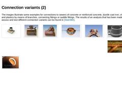
The images illustrate some examples for connections to sewers of concrete or reinforced concrete, ductile cast iron, vitrified clay and plastics by means of branches, connecting fittings or saddle fittings. The results of an analysis that has been made in order to assess and test different connection variants can be found in [Stein96h]. (Image: Examples for connections – Saddle fitting of ductile cast iron) (Image: Screwable saddle fitting of GRP) (… |
|
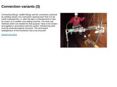
Connecting fittings, saddle fittings and the connection achieved by welding require one connection opening each that is to be made subsequently, i.e. after the pipe is manufactured or laid, by means of a suitable core drilling machine. The tools and methods which are needed for that purpose “have to be chosen and applied in accordance with the system. Reinforcing steel must be protected against corrosion. The permanent leaktightness of the connection … |
|
The way of connecting drains and laterals to sewers which has its origin in the 19th century at the beginning of modern sewerage technology has always been recognised as weakness of the system that resulted in the following facts: -
Especially in the intra-urban area, the concentration of connections can be quite dense, whereby distances between inlets of 1 to 2 m are not uncommon,
-
Subsequently made connections to non-accessible …
|
|
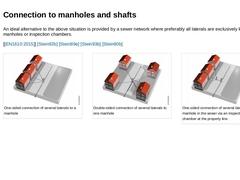
An ideal alternative to the above situation is provided by a sewer network where preferably all laterals are exclusively led into manholes or inspection chambers. [ [EN1610:2015]] [Stein92b] [Stein89e] [Stein93b] [Stein80b] (Image: Connection variant of laterals to manholes) (Image: Connection variant of laterals to manholes) (Image: Connection variant of laterals to manholes) |