|

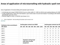
Area of application of microtunnelling with hydraulic spoil removal: -
nominal pipe size range of DN/ID 200 (8 in) up to a clear width of < 1200 mm (48 in) and a jacking distance of ≤ 500 m
-
usually straight bores, loose soil of soil classes L (up to stone class S 4) and rock classes F according to DIN 18319, in groundwater up to max. 30 m
-
minimum depth of cover ≥ 2 DN/OD, but at least 1.8 m
(Table: Areas of application of microtunnelling with hydraulic … |
|
|

The jacking performance of microtunnelling with hydraulic spoil removal is subject to the following influences: -
subsoil conditions
-
jacking distance
-
jacking technology (design of the cutting head)
-
number and qualification of the personnel (especially the experience of the machine operator)
-
construction-site-specific boundary conditions (e.g. space)
-
jacking pipe (nominal size, material quality)
-
additional and auxiliary measures
-
the capacity …
|
|
|

|
(Image: Pros and cons)
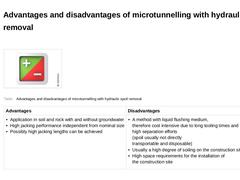
(Table: Advantages and disadvantages of microtunnelling with hydraulic spoil removal) |
|
|

|
|

|
(Image: Microtunnelling with pneumatic spoil removal) |
|
(Image: Equipment, possible arrangement of the components on the construction site and space requirements (approximately L x W = 34 x 4 m) in microtunnelling with pneumatic spoil removal - plan view (on the model of the jacking of pipes DN/ID 600, pipe length 2.0 m)) |
|
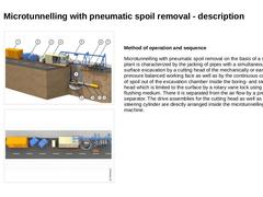
Method of operation and sequence Microtunnelling with pneumatic spoil removal on the basis of a suction plant is characterized … |
|
|

Experience gathered at sites [Reith98] has shown that they are at their best in cohesive soils with a large percentage of particle sizes < 0.5 mm. The main advantages here are economic as the separation plants required with hydraulic spoil removal for separating the slurry are less effective in this size range. Area of application of microtunnelling with pneumatic spoil removal: -
nominal pipe size range of DN/ID 200 (8 in) up to a clear width < 1200 …
|
|

The jacking performance of microtunnelling with pneumatic spoil removal is subject to the following influence: -
subsoil conditions and type of soil (cohesive, non-cohesive)
-
jacking distance
-
jacking technology (design of the cutting head)
-
number and qualification of the personnel (especially the experience of the machine operator)
-
construction-site-specific boundary conditions (e.g. space)
-
jacking pipe (nominal pipe size, material, quality)
|
|

|
(Image: Pros and cons)
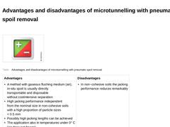
(Table: Advantages and disadvantages of microtunnelling with pneumatic spoil removal) |
|
|

|
|

|
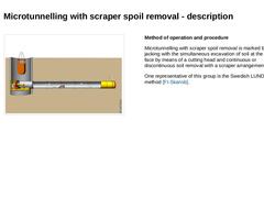
(Image: Microtunnelling with spoil removal by other mechanical means (spoil removal by a scraper arrangement)) |
Method of operation and procedure
Microtunnelling with scraper spoil removal is marked by pipe jacking with the simultaneous excavation of soil at the work face by means of a cutting head and continuous or discontinuous soil removal with a scraper arrangement.
One representative of this group is the Swedish LUNDBY method [FI-Skansb]. |
|
|

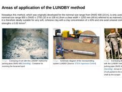
Nowadays this method, which was originally developed for the nominal size range from DN/ID 400 (16 in), is only used in the nominal size range 800 ≤ DN/ID ≤ 2750 (32 in to 108 in) (from a clear width > 1200 mm (48 in) referred to as manned pipe jacking). It is therefore ideally suitable for very soft, cohesive clay with a clay concentration of ≥ 40% and one-axial uniaxial compressive strengths ≤ 0.05 N/mm2. (Image: Conveying of soil with the LUNDBY … |

|

|
Area of application of the LUNDBY method: -
nominal pipe size range from DN/ID 800 (32 in) up to a clear width < 2750 mm (108 in) and a jacking distance ≤ 150 m (492 ft)
-
usually straight bores; cohesive, saturated soil of classes LBM 1/LBO 1 with N-values ≤ 4
|
|
(Image: Attention!)
Empirical value for the jacking performance in the LUNDBY method: 1.25 to 4.2 m/h |
|

|

|
|

|
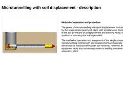
(Image: Microtunnelling with soil displacement) |
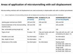
Method of operation and procedure The group of microtunnelling with spoil displacement is characterized by the single-phase jacking of pipes with simultaneous displacement of the soil by means of a displacement and steering head, e.g. no system for removing the soil is provided. The method of operation and equipment of the single-phase microtunnelling method with soil displacement are basically identical … |
|
|

|
Microtunnelling methods with soil displacement are used exclusively in displaceable soils with or without groundwater. (Table: Areas of application of microtunnelling methods with soil displacement according to the manufacturer's information) |
|

|

|
|

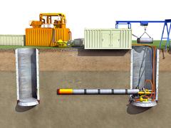
Micro tunnelling refers to unmanned, remote-controlled methods for jacking pipes. This module covers the various methods, in particular, micro tunnelling with hydraulic, pneumatic, auger and scraper conveyance and soil displacement. The focus is on single- and two-phase micro tunnelling, the technical components in micro tunnelling and areas of application. After completion of this module, you will have a sound knowledge of: -spectrum of process technologies;
-machine and control components and
-their functions;
-advantages and disadvantages as well as
-areas of application. |
|

Today, supply and discharge lines are still predominantly installed using the open-cut method. This involves digging a trench, installing the lines under the protection of an embankment or sheeting, and subsequently refilling the trench. However, due to numerous disadvantages and growing public environmental awareness, it is becoming increasingly important to consider trenchless technology as a viable alternative. Trenchless technology offers significant … |
|

|
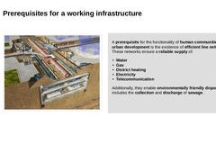
(Image: Overview of the present underground infrastructures) |
A functional and efficient line network is a fundamental prerequisite for the functioning of human communities and urban development. Such networks ensure a reliable supply of: -
Water
-
Gas
-
District heating
-
Electricity
-
Telecommunication
Additionally, they enable environmentally friendly disposal, which includes the collection and discharge of sewage. |
|

|

|
|

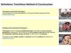
Trenchless construction technique:
Any technique for constructing pipelines underground without the need to open trenches [DINEN12889:2000]. |
|
(Image: Shield machine arriving in the target shaft) |
|
(Image: Microtunnelling machine with pneumatic spoil removal (method AVP [FI-Herreb]) - Scraper cutting head with view of the rotary vane lock behind the excavation chamber) |
|
(Image: Microtunnelling machine with auger spoil removal ? cutting head) |
|
|
|
…
|

|

|
|

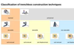
| (Image: Manned techniques)
manned | (Image: Unmanned techniques)
unmanned | | (Image: Steerable techniques)
steerable | (Image: Steerable techniques)
steerable | (Image: Non-steerable techniques)
non-steerable | | (Image: Soil removal techniques)
soil removal | (Image: Soil removal techniques)
soil removal | (Image: Soil displacement techniques)
soil displacement | (Image: Soil removal techniques)
soil removal | (Image: Soil displacement techniques)
soil displacement… |
|
|

|
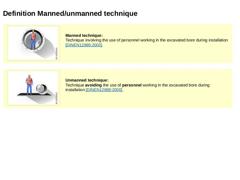
(Image: Manned techniques) Manned technique:
A method in which personnel work inside the excavated bore during the installation process [DINEN12889:2000]. |
|
|
|
(Image: Unmanned techniques) Unmanned technique:
A method that avoids the use of personnel working inside the excavated bore during the installation process [DINEN12889:2000]. |
|
|

|
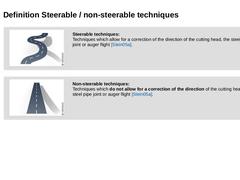
(Image: Steerable techniques)
Steerable techniques:
Techniques which allow for a correction of the direction of the cutting head, the steel pipe joint or auger flight [Stein05a]. |
|
|
|
(Image: Non-steerable techniques)
Non-steerable techniques:
Techniques which do not allow for a correction of the direction of the cutting head, the steel pipe joint or auger flight [Stein05a]. |
|