|
|
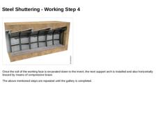
(Image: Working steps for gallery techniques (heading) with steel shuttering) |
|
Once the soil of the working face is excavated down to the invert, the next support arch is installed and also horizontally braced by means of compressive brace.
The above mentioned steps are repeated until the gallery is completed. |
|
|
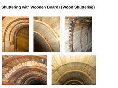
(Image: Gallery technique (heading) with wood shuttering and stable working face (S&P)) (Image: Gallery techniques (heading) with wood shuttering - wood shuttering wedged against support arches) (Image: Gallery techniques (heading) with wood shuttering) (Image: Gallery techniques (heading) with wood shuttering - wood shuttering wedged against support arches) (Image: Gallery techniques (heading) with wood shuttering - wood shuttering wedged against … |
|
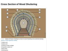
(Image: Gallery techniques (heading) by means of wood forepoling (cross-sectional drawing)) |
|
|
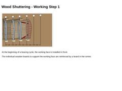
(Image: Working steps for gallery techniques (heading) (sewer to be replaced not shown)) |
|
At the beginning of a bracing cycle, the working face is installed in front. The individual wooden boards to support the working face are reinforced by a board in the centre. |
|
|
|
(Image: Working steps for gallery techniques (heading) (sewer to be replaced not shown)) |
|
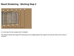
In a next step, the next support arch is installed. The wooden boards that support the working face are wedged against this support arch and the board in the centre is removed. |
|
|
|
(Image: Working steps for gallery techniques (heading) (sewer to be replaced not shown)) |
|
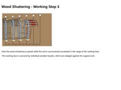
Now the wood shuttering is jacked while the soil is successively excavated in the range of the working face. The working face is secured by individual wooden boards, which are wedged against the support arch. |
|
|
|
(Image: Working steps for gallery techniques (heading) (sewer to be replaced not shown)) |
|
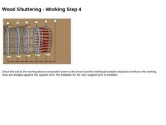
Once the soil at the working face is excavated down to the invert and the individual wooden boards to reinforce the working face are wedged against the support arch, the bedplate for the next support arch is installed. |
|
|
|
(Image: Working steps for gallery techniques (heading) (sewer to be replaced not shown)) |
|
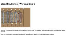
In order to install the new support arch, the board in the center is integrated again and the support of the working face is braced. Now the support arch is installed and wedged at the working face by the individual wooden boards. |
|
|
|
(Image: Working steps for gallery techniques (heading) (sewer to be replaced not shown)) |
|
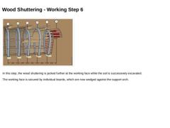
In this step, the wood shuttering is jacked further at the working face while the soil is successively excavated. The working face is secured by individual boards, which are now wedged against the support arch. |
|
|
|
(Image: Working steps for gallery techniques (heading) (sewer to be replaced not shown)) |
|
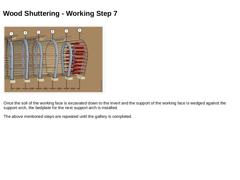
Once the soil of the working face is excavated down to the invert and the support of the working face is wedged against the support arch, the bedplate for the next support arch is installed.
The above mentioned steps are repeated until the gallery is completed. |
|

|
(Video: Gallery technique - Wood shuttering) Video: Gallery technique - Wood shuttering [Image: S&P GmbH]. This interactive object is only visible in the online version of the module. |
|
|
(Image: Gallery techniques (heading) sewer to be replaced has been exposed) [Scher78]) |
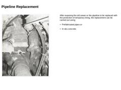
After exposing the old sewer or the pipeline to be replaced with the protection of temporary lining, the replacement can be carried out using: -
Prefabricated pipes or
-
In-situ concrete.
|
|
|
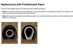
There are two available options for replacement with prefabricated pipes: -
Option 1: laying the temporary by-pass pipelines, removing the pipeline to be replaced, laying the new pipeline, switching over the laterals and removing the temporary by-pass pipelines.
-
Option 2: laying the new pipeline immediately parallel to the one being replaced, switching over the laterals and removing the pipeline to be replaced.
(Image: Possibilities of interior work … |
|
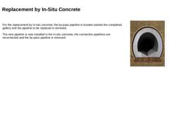
For the replacement by in-situ concrete, the by-pass pipeline is located outside the completed gallery and the pipeline to be replaced is removed. The new pipeline is now installed in the in-situ concrete, the connection pipelines are reconnected and the by-pass pipeline is removed. |
(Image: Possibilities of interior work using gallery techniques (heading) with reference to [Düsse] [Image: S&P GmbH]) |
|
|
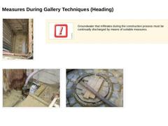
(Image: View to the gallery invert in the range of the starting excavation) (Image: Attention!) Groundwater that infiltrates during the construction process must be continually discharged by means of suitable measures. (Image: Submersible pump to discharge strata water) (Image: Discharge of strata water into the sewage system) |
|
|
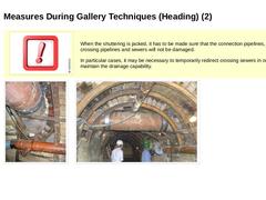
(Image: Attention!) When the shuttering is jacked, it has to be made sure that the connection pipelines, crossing pipelines and sewers will not be damaged. In particular cases, it may be necessary to temporarily redirect crossing sewers in order to maintain the drainage capability. |
|
(Image: Provisional redirection of a crossing sewer) |
(Image: Provisional redirection of a crossing sewer) |
|
|
|
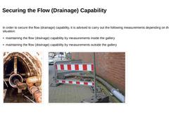
In order to secure the flow (drainage) capability, it is advised to carry out the following measurements depending on the local situation: |
|
(Image: New sewer in the gallery with incoming provisional drainage capability sewer [Düsse]) |
(Image: Water drainage) |
|
|
|
Role of annular space grouting: -
secure the new pipeline (positional stabilisation)
-
creating a defined bedding in the gallery
-
equal distribution of external loads
-
preventing the creation of dangerous gas pockets.
|
|
(Image: Pros and cons) |
Further advantages of annular space grouting: -
preventing the collapse of the gallery and therefore preventing of settlements at the ground surface
-
buoyancy prevention of the new pipeline
-
compensation of different, …
|
|
|
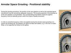
During the grouting procedure, the position of the new pipeline as well as the potential lateral connections must be secured by adequate measures. The buoying upwards or the bending up of the new pipeline is not permitted. The corresponding preventative measures against buoyancy must be statically proven within the scope of quality assurance
In order to avoid the buoyancy of the new pipeline during the annular space grouting or to reduce the buckling … |
|
|
|
(Image: Attention!) If the cross sections or the filling volume are very large, the annular space grouting must be carried out in sections. Ideally, the grouting is carried out in three steps. |
|
|
|
(Image: Working steps for annular space grouting of huge cross sections)
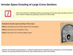
Example of annular space grouting in three steps: Phase 1: grouting up to the bottom edge of the new pipeline. Phase 2: grouting up to the pipeline crown. Phase 3: grouting of the remaining … |
|
|
|
(Image: Documentation) |
During the annular space grouting, the following quality-affecting parameters within the scope of quality assurance must continually be monitored and recorded: -
safety against buoyancy and ballasting of the new pipeline
-
grouting pressure (the buckling pressure of the new pipeline must not be exceeded)
-
actual/design volume of the grouting material
-
material characteristics of the grouting material
-
spreading dimension, flow …
|
|
|
|
|
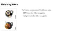
(Image: Inspection) (Image: Leaktightness) The finishing work consists of the following tasks: |

|
|
|
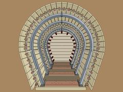
This module focuses on the fundamentals of the trenchless replacement of gas, water, wastewater pipelines using the gallery techniques known from the mining industry. In addition, the individual steps of the gallery heading process with steel and timber support are described - from the preparatory measures to the final work. In addition, the areas of application and limitations of gallery heading, the measures for quality assurance as well as the advantages and disadvantages of this method are presented. After completing this module, you will have a sound knowledge of: - characteristics of gallery heading;
- working steps of this form of heading;
- relevant aspects for quality assurance.
|