|

|
|
Today, the installation of gas, water and wastewater pipelines is still predominantly carried out using open trenches. In view of the numerous disadvantages associated with this method, it is imperative that trenchless pipeline construction be considered much more strongly in the future than it has been to date as an alternative in the planning and construction of sewers and pipelines. This module deals in detail with the procedure and the various components. Emphasis is placed on the different types of shield machines, excavation tools, separation systems, the control and steering station, injection/grouting agent and soil extraction and reprocessing. After completing this module, you will have a sound knowledge of: - all components of pipe jacking and
- their function and tasks.
|
|
Today, supply and discharge lines are still predominantly installed by using the open-cut method: a trench is dug, the lines are installed. Under the protection of an embankment or sheeting and the trench is filled afterwards. In the face of the numerous disadvantages as well as the citizens' growing environmental consciousness in the future it is urgently necessary to take trenchless technology into account much stronger than until today as an alternative … |
|
|
(Image: Unmanned techniques) |
|
(Image: Steerable techniques) |
|
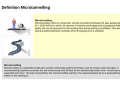
Microtunnelling:
Microtunnelling refers to unmanned, remote-controlled techniques for pipe jacking (jacking pipe ID < 1200 (48 in)) in which, for reasons of machine technology and occupational health and safety, the use of personnel on the working face during jacking is prohibited. This also applies during troubleshooting for example when the jacking is at a standstill. |
Microtunnelling |
|
|
|
(Image: Unmanned techniques) |
|
(Image: Steerable techniques) |
|
(Image: Soil removal techniques) |
|
(Image: Soil displacement techniques) |
|
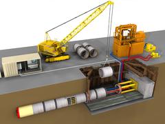
In microtunnelling methods, jacking pipes are jacked (in one or two phases) from a starting shaft with the aid of a jacking station (in exceptional cases also using additional intermediate jacking stations) up to a target shaft. At the same time an unmanned, remote controlled microtunnelling machine carries out … |
|
|
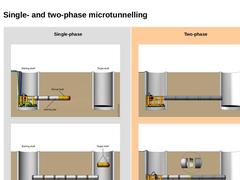
Single-phase |
(Image: Single-phase jacking - Jacking)
|
|
(Image: Single-phase jacking - Completed pipeline)
|
| Two-phase |
(Image: Two-phase jacking - Phase 1)
|
|
(Image: Two-phase pipe jacking - Phase 2)
|
|
|
|
|
(Image: Soil removal techniques) |
|
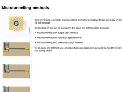
(Image: Microtunnelling with auger spoil removal) |
|
(Image: Microtunnelling with hydraulic spoil removal) |
|
(Image: Microtunnelling with pneumatic spoil removal) |
|
The unmanned, steerable microtunnelling techniques employed base generally on the principle of soil removal. Depending on the way of conveying the spoil, it is differentiated between: |
|
|
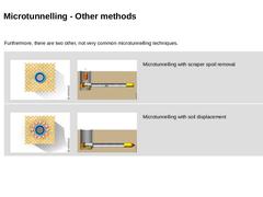
Furthermore, there are two other, not very common microtunnelling techniques. |
|
(Image: Soil removal techniques) |
(Image: Microtunnelling with spoil removal by other mechanical means (spoil removal by a scraper arrangement)) |
Microtunnelling with scraper spoil removal |
|
(Image: Soil displacement techniques) |
(Image: Microtunnelling with soil displacement) |
Microtunnelling with soil displacement |
|

|
|
|
|
(Image: Technical components in microtunnelling) |
|
(Image: Equipment, possible arrangement of the technical components on the construction site and space requirement in microtunnelling with auger spoil removal - top view) |
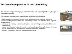
The technical components employed in microtunnelling vary depending on the way the spoil or cuttings are removed. The following components are employed with all kinds of microtunnelling: -
jacking station (consisting of jacking frame, …
|
|
|
|
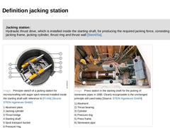
Jacking station:
Hydraulic thrust drive, which is installed inside the starting shaft, for producing the required jacking force, consisting of jacking frame, jacking cylinder, thrust ring and thrust wall [Stein05a]. |
|
(Image: Principle sketch of a jacking station for microtunnelling with auger spoil removal installed inside the starting shaft) (Image: Press station in the starting shaft for the jacking of stoneware pipes in 1980) |
|
|
|
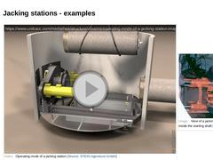
(Video: Operating mode of a jacking station)
| (Image: View of a jacking station for microtunnelling that is mounted inside the starting shaft)
| | (Image: Jacking station)
| (Image: Jacking station with abutment plate)
|
|
|
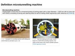
Microtunnelling machine:
Displaceable construction for unmanned jacking of jacking pipes with a clear diameter < 1200 mm (48 in) (not to be confused with DN/ID) consisting of boring and steering head as well as trailing shield segment(s) (with reference to [DS853]). (Image: Example of a tunneling machine with drilling and control head and back-up) (Image: View from behing into the open control head of a LOVAT-MTS tunneling machine) |
|
|
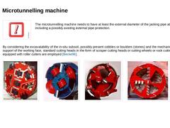
(Image: Attention!)
The microtunnelling machine needs to have at least the external diameter of the jacking pipe at least including a possibly existing external pipe protection. |
|
By considering the excavatability of the in-situ subsoil, possibly present cobbles or boulders (stones) and the mechanical support of the working face, standard cutting heads in the form of scraper cutting heads or cutting wheels or rock cutting heads equipped with roller … |
|
|
|
(Image: Attention!) |
In microtunnelling the whole pipe string in the form of a linked chain must follow the microtunnelling machine. Thus the bore path must necessarily also be the line and gradient of the final line. This means that all deviations from the design position remain almost unchanged as errors. |
|
(Video: Principle of linked chain during jacking) Video: Principle of linked chain during jacking [Image: S&P GmbH]. This interactive object … |
|
|
Steerability (also known as controllability) is achieved because the microtunnelling machine consists of two parts linked together by an articulated joint - the boring/ steering head and the trailing shield segment. The steering head can be angled in any direction by means of steering cylinders operated from a control and steering desk. (Video: Steering of the shield machine by means of steering cylinders) Video:Steering of the shield machine by means … |
|
|
(Image: Examples of cross sectional shapes of starting shafts in microtunnelling [FI-Herreb] - Circular (open sinking shaft), jacking cylinder arranged parallel to the jacking pipe/to the microtunnelling machine) |
|
(Image: Entry of the microtunnelling machine into the target shaft) |
|
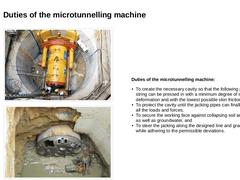
Duties of the microtunnelling machine: -
To create the necessary cavity so that the following pipe string can be pressed in with a minimum degree of soil deformation …
|
|
|
|
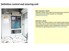
(Image: Control and steering unit) |
Main operator's stand:
Operator's stand, from where the boring process and the forward movement of the shield machine are controlled [DINEN12336:2010]. |
|
Operator's stand:
Any place of a shield machine or the trailing shield segment, from where one or several functions of the shield machine, the trailing shield machine or their independent function units are controlled by operating personnel [DINEN12336:2010] |
|
|
|
|
|
(Image: Technical components for microtunnelling with auger spoil removal in single phase jacking) |
|
(Image: Equipment, possible arrangement of the components on the construction site and space requirement (approximately L × W = 22.0 × 4.0 m) in microtunnelling with auger spoil removal - top view (on the model of the jacking of pipes DN/ID 600, pipe length 2.0 m)) |
|
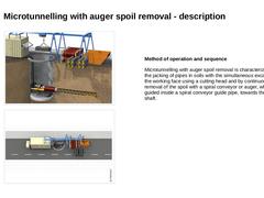
Method of operation and sequence Microtunnelling with auger spoil removal is characterized … |
|
|
|
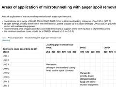
Area of application of microtunnelling methods with auger spoil removal: -
nominal pipe size range of DN/ID 250 to DN/ID 1000 (10 in to 40 in) and jacking distances of up 150 m (500 ft)
-
straight borings, usually loose soil of the soil classes L (stone classes up to S2) according to DIN 18319, in groundwater up to 6 m with additional equipment
-
recommended area of application for a controlled mechanical support of the working face ≤ DN/ID 800 (32 …
|
|
|
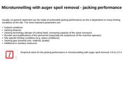
Usually, no general statement can be made of achievable jacking performance as this is dependent on many limiting conditions at the site. The most important parameters are: -
Subsoil conditions
-
Jacking distance
-
Jacking technology (design of cutting head, conveying capacity of the spiral conveyor)
-
Number and qualifications of the personnel (especially the experience of the machine operator)
-
Site-specific limiting conditions (e.g. space conditions)
|
|

|
|
(Image: Pros and cons)
(Table: Advantages and disadvantages of microtunnelling with auger spoil removal) |
|
|
|
|
|
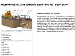
(Image: Microtunnelling with hydraulic spoil removal in single phase jacking) |
|
(Image: Basic equipment, possible arrangement components on the construction site and space requirements (ca. L × B = 35 × 4 m) for microtunnelling with hydraulic spoil removal - plan view (on the model of the jacking of pipes DN/ID 600, pipe length 2.0 m)) |
|
Method of operation and sequence Microtunnelling with hydraulic spoil removal is characterized by the jacking … |
|
