|
For reasons of safety, excavations and trenches with sloping walls, as well as sloped edges, are only to be accessed after the stability of the earth or rock walls is ensured. This also holds true for excavations and trenched yet to be lined, for as long as the respective shoring has not been inserted [DIN4124:2002]. |
|
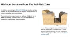
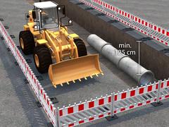
In addition, according to [DIN4124:2002], protective strips have to be established around the edge of the excavation or trench, as well as at access points. These protective strips have to be at least 2 ft (0.61 m) in width, preferably horizontal and have to be kept free of excavation material and other obstacles. (Image: Safeguarding of trenches and shafts without lining for depths > 4 ft / 1.25 m and ≤ 6 ft / 1.75 m in accordance with [DIN4124c] – … |

|
|

|
Animation: Exercise Work safety - Minimum working distance [Animation: visaplan GmbH]. This interactive object is only visible in the online version of the module. |

|
Animation: Exercise Work safety - Excavator – Danger zone [Animation: visaplan GmbH]. This interactive object is only visible in the online version of the module. |

|
Animation: Exercise Work safety - Traffic control [Animation: visaplan GmbH]. This interactive object is only visible in the online version of the module. |

|
Congratulations! You have successfully finished this lesson. Next you will have the opportunity to review the newly acquired knowledge with an interactive questionnaire. You can of course still navigate back to any point in the lessons if you wish to review a specific point or subject. Stay curious! |
|
The aspects of occupational health and safety that must be taken into account in the context of civil engineering work, especially in the construction of pipelines and sewers using the open cut method, are very diverse. They harbor a considerable potential for danger for those working on the construction site, but also for uninvolved persons. After completing this module, you will have knowledge regarding: - risks and hazardous areas;
- securing construction sites in traffic areas;
- tools and equipment for safe working.
|
|
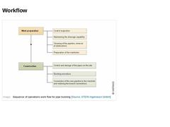
(Image: Sequence of operations work flow for pipe bursting) |
|
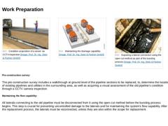
(Image: Condition acquisition of a sewer via CCTV-inspection) (Image: Maintaining the drainage capability) (Image: Exposing a lateral connection using the open cut method as part of the bursting process) Pre-construction survey: The pre-construction survey includes a walkthrough at ground level of the pipeline sections to be replaced, to, determine the location of existing pipelines and utilities in the surrounding area, as well as acquiring a visual … |
|
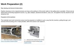
Pipe cleaning, and removal of obstructions: Pipeline cleaning is not a required process as long as the pulling-in of the winch cable or the pulling rods is possible. If there are any obstructions preventing equipment access, e.g. pipe collapse, positional deviations, roots, etc., the pipeline must be cleared of such obstacles first. Preparation of the manholes: The manhole invert and connection areas must be prepared or modified in such a way that the … |
|
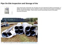
Upon arrival at the construction site, the pipes are to be inspected for defects and damages. In addition, the delivery papers must be checked in order to ensure that the product corresponds with the original order details. These checks must be documented as part of the quality assurance procedure. (Image: HDPE discrete long pipes DA 20 in (500 mm)) |
|
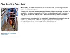
(Image: Bursting head with a directional guide) Pipe bursting procedure: Installation of the new pipeline while considerating permissible tensile forces and bending radii. There must be an overlap between the external diameter of the expander head and that of the new pipeline in order to reduce the frictional forces during the pulling through procedure. In other words, the expander head will have a larger diameter than the new pipe that will be pulled … |
|
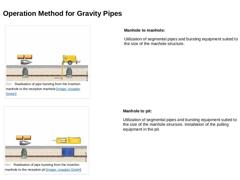
(Image: Realisation of pipe bursting from the insertion manhole to the reception manhole) Manhole to manhole: Utilization of segmental pipes and bursting equipment suited to the size of the manhole structure. (Image: Realisation of pipe bursting from the insertion manhole to the reception pit) Manhole to pit: Utilization of segmental pipes and bursting equipment suited to the size of the manhole structure. Installation of the pulling equipment in the … |
|
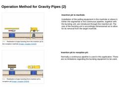
(Image: Realisation of pipe bursting from the insertion pit to the reception manhole) Insertion pit to manhole: Installation of the pulling equipment in the manhole or above it. Either the segmental or the continuous pipeline, together with the bursting unit, are introduced through the insertion pit. The size of the bursting unit is accordingly dimensioned as to allow for its removal from the target manhole. (Image: Realisation of pipe bursting from … |
|
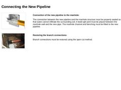
(Image: Connection of the new pipeline to the manhole) Connection of the new pipeline to the manhole: The connection between the new pipeline and the manhole structure must be properly sealed so that water cannot infiltrate the surrounding soil. A leakt-ight joint must be placed between the manhole wall and the new pipe. The manhole channel and benching must be fitted to the new pipeline. (Image: Re-connection of a lateral to the new pipeline with the … |

|
|

|
|
|
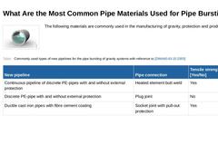
(Image: Gravity pipeline) The following materials are commonly used in the manufacturing of gravity, protection and product, pipes. (Table: Commonly used types of new pipelines for the pipe bursting of gravity systems with reference to [DWAM143-15]) |
|
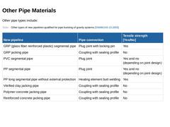
Other pipe types include: (Table: Other types of new pipelines qualified for pipe bursting of gravity systems) |

|
(Image: Gravity pipeline) If polyethylene pipes are to be used, only PE 100 or PE-Xa pipes should be considered. |
Material |
Pipe joint |
External protection |
|
PE 100 |
Connection using a heated butt joint and removal of the weld bead |
External protection is necessary and is to be restored in the weld area. |
|
PE-Xa |
None, only use with coiled pipes, because the welding of PE-Xa is only possible with electrofusion couplers. |
Not required due to the durability … |
|
|
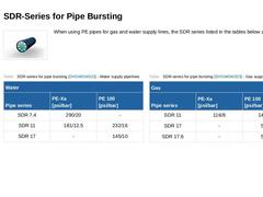
(Image: Rohricon) When using PE pipes for gas and water supply lines, the SDR series listed in the tables below apply. (Table: SDR-series for pipe bursting - Water supply pipelines) (Table: SDR-series for pipe bursting - Gas supply pipelines) |
|
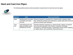
(Image: Rohricon) The following table presents external protection requirements for steel and cast iron pipes. |
Material |
Joint |
External protection |
|
Steel |
Welded joints according to DVGW work sheet GW 350 |
External protection is required (e.g. cement mortar coating or glass fiber reinforced synthetic resin laminates); outside weld area to be flush ground (constant outer diameter) |
|
Cast iron |
Axial-locking joint and rigid connection as per GW368 and … |
|

|
|
|
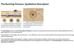
(Image: Qualitative description of the pneumatic bursting process) (Image: Model of a cylindrical cavity expansion in ideal elasto-plastic material with reference to [Zimme88] [Image: S&P GmbH]) The first phase of the so-called Secondary Condition I involves the bursting of the old sewer and the radial displacement of the pipe fragments in the surrounding soil. Subsequently, the soil settles into the overcut ( i.e., the difference in the cross section) … |