
|
In the given case of application, hydrogeological investigations are particularly used to determine the: -
Groundwater level
-
Flow velocity and direction
-
Permeability
-
Accruing water quantity
-
Hydrostatic pressure condition
-
Chemistry of the groundwater
|
|
The knowledge of the site-specific hydrogeological conditions has a significant influence on the selection of the individually appropriate inspection-, construction- or rehabilitation method. Furthermore, in conjunction with the in situ soil, conclusions can be drawn with regard to possible water retention measures and their potential consequences, e.g. when creating small building pits for repair measures from outside or when replacing drains and … |
|
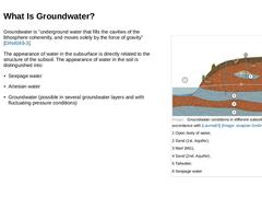
(Image: Groundwater conditions in different subsoil strata in accordance with [Lauma83]) Groundwater is "underground water that fills the cavities of the lithosphere coherently, and moves solely by the force of gravity" [DIN4049-3]. The appearance of water in the subsurface is directly related to the structure of the subsoil. The appearance of water in the soil is distinguished into: |
|
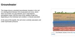
The image shows a standard groundwater situation in the soil. It is distinguished between the unsaturated soil zone, which does not contain any groundwater, but is saturated by precipitation water, and the area of the capillary fringe that, depending on the individual soil condition, is heavily saturated. In the area of the aquifer, the soil zone is entirely saturated, and under hydrostatic pressure. (Image: Groundwater situation in the soil) |
|
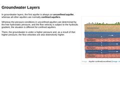
(Image: Aquifer confined/unconfined) In groundwater layers, the first aquifer is always an unconfined aquifer, whereas all other aquifers are normally confined aquifers. Whereas the pressure conditions in unconfined aquifers are determined by the free hydrostatic pressure, and the flow velocity is subject to the hydraulic gradient, the situation is different for confined aquifers. There, the groundwater is under a higher pressure and, as a result of … |
|
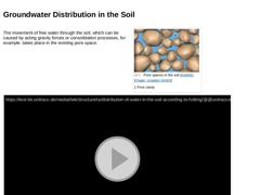
The movement of free water through the soil, which can be caused by acting gravity forces or consolidation processes, for example, takes place in the existing pore space. (Image: Pore cavity in the soil [Hölti96]) Video: Distribution of water in the soil (according to Hölting, 1994) [Animation: visaplan GmbH]. This interactive object is only visible in the online version of the module. (Video: Distribution of water in the soil according to Hölting) |
|
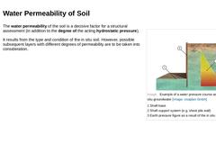
(Image: Example of a water pressure course as a result of the in situ groundwater) The water permeability of the soil is a decisive factor for a structural assessment (in addition to the degree of the acting hydrostatic pressure). It results from the type and condition of the in situ soil. However, possible subsequent layers with different degrees of permeability are to be taken into consideration. |

|
|
|
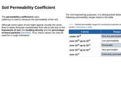
The permeability coefficient k (also
called kf) is used to measure the permeability of the soil. Although some types of soil might appear visually the same, their k-values fluctuate considerably from site to site due to the framework of soil, the bedding density and the percentage of finest particles [Herth95]. Thus, these values can only be used for a rough estimation. For civil engineering purposes, it is distinguished between the following permeability … |
|
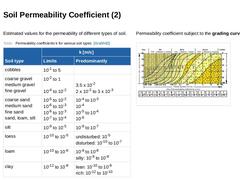
Estimated values for the permeability of different types of soil. (Table: Permeability coefficients k for various soil types) Permeability coefficient subject to the grading curves. (Image: Permeability coefficient with reference of the particle size distribution curve [LWA89] [FI-Herreb]) |
|
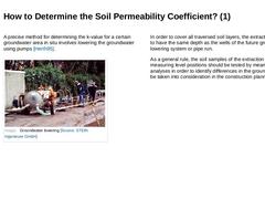
A precise method for determining the k-value for a certain groundwater area in situ involves lowering the groundwater using pumps [Herth95]. (Image: Groundwater lowering) In order to cover all traversed soil layers, the extraction well has to have the same depth as the wells of the future groundwater lowering system or pipe run. As a general rule, the soil samples of the extraction well and all measuring level positions should be tested by means of … |
|
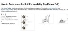
Prior to the design and dimensioning of technical details, investigations according to [[ASTM D2434]] and/or [DIN18130-1:1998] should also be included. Their evaluation is based on the application of Darcy‘s law and, as a result, provides the permeability coefficient k. (Formula: Permeability coefficient k according to Darcy‘s law) (Image: Filter velocity v = Q (flow) / A (cross section)) (Image: Examples of permeability tests [Soos96] - Test arrangement … |
|
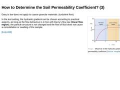
(Image: Influence of the hydraulic gradient onto the permeability coefficient) Darcy‘s law does not apply to coarse granular materials (turbulent flow). In the test setting, the hydraulic gradient can be chosen according to practical aspects, as long as the flow behaviour is in line with Darcy‘s flow law (linear flow region), the particle structure is not changed and the flow of fluid does not cause a consolidation or swelling of the sample. [Kolym98] |
|
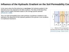
(Image: Influence of the average grain diameter d onto the limits of the linear region of the filter flow law) In the cases where the flow behaviour is non-linear, the hydraulic gradient in the laboratory has to be adjusted to the field conditions. The limits of the linear flow region can be roughly estimated subject to the average particle diameter [DIN18130-1:1998]. Thus, for water permeability tests under prelinear or postlinear conditions in the … |
|
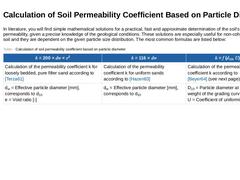
In literature, you will find simple mathematical solutions for a practical, fast and approximate determination of the soil's water permeability, given a precise knowledge of the geological conditions. These solutions are especially useful for non-cohesive types of soil and they are dependent on the given particle size distribution. The most common formulas are listed below: (Table: Calculation of soil permeability coefficient based on particle diameter) |

|
As the solution to his determined interrelations, Beyer provides an easy-to-handle nomogram, from which you can directly read off the water permeability for sands and gravels [Beyer64]. However, this method does not take sufficient account of decisive influencing factors (as e.g. the given bedding density). Thus, reliable data for the individual case of application can only be gathered by means of a test arrangement for the determination of the water … |

|
|

|
|

|
Congratulations! You have successfully finished this lesson. Next you will have the opportunity to review the newly acquired knowledge with an interactive questionnaire. You can of course still navigate back to any point in the lessons if you wish to review a specific point or subject. Stay curious! |
|
The construction of sewers is often carried out using the open construction method. Depending on the design, this results in pipe-soil systems with different external loads on the sewer. To understand these relationships, the soil mechanical and hydrogeological principles for characterizing the subsoil are explained. After completing this module, you will have a sound knowledge of how: - to differentiate between soil types;
- to identify the influences of grain shape and grain size distribution on the practical construction properties of the subsoil and
- to name the different appearances of water in the subsoil;
- to determine the water permeability of the soil for a constructional assessment of the soil.
|
|
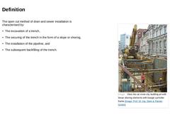
The open cut method of pipeline installation is characterised by: -
The excavation of a trench,
-
The securing of the trench in the form of a slope or shoring,
-
The installation of the pipeline, and
-
The subsequent backfilling of the trench.
(Image: View into an inner-city building pit with linear shoring elements with boogie car/roller frame) |

|
(Image: Example of subsoil risks) The planning stage requires information regarding the projected construction and the local boundary conditions. It appeared in practice that especially the following criteria are to be considered: -
Type and condition of the subsoil
-
Groundwater conditions
-
Pipe run and depth
-
Material and dimensions of the pipes to be installed
-
Securing of adjacent structures above- and below ground (spacing, depth of foundation, …
|
|
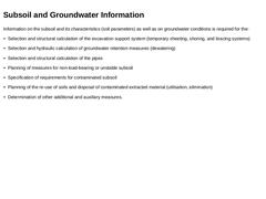
Information on the subsoil and its characteristics (soil parameters) as well as on groundwater conditions is required for the: -
Selection and structural calculation of the excavation support system (temporary sheeting, shoring, and bracing systems)
-
Selection and hydraulic calculation of groundwater retention measures (dewatering)
-
Selection and structural calculation of the pipes
-
Planning of measures for non-load-bearing or unstable subsoil
-
Specification …
|
|
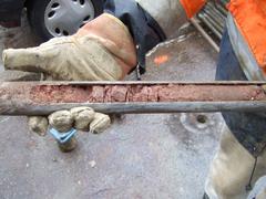
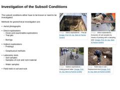
The subsoil conditions either have to be known or need to be investigated. Methods for geotechnical investigation are: -
Aerial photographs
-
Direct explorations
-
Given and examinable explorations
-
Trial pits
-
Borings
-
Indirect explorations
-
Probings
-
Geophysical methods
-
Laboratory tests
-
Soil samples
-
Samples of rock and rock material
-
Water samples
-
Field trials in soil and rock
(Image: Direct explorations – Trial pit) (Image: Direct explorations – … |
|
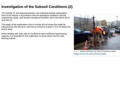
(Image: Subsoil exploration by means of dynamic probing) The number of, and spacing between, the individual subsoil explorations have to be chosen in accordance with the geological conditions and the engineering needs, and should normally be between 165 ft and 655 ft (50 m and 200 m). The depth of the explorations has to include all soil strata that might be influenced by the structure, and has to extend to at least 7 ft (2 m) below the trench base. |