
|

|
(Image: Attention!)
A scheduled change of method by conversion can only be carried out with shield types that are further developed for this purpose. |
|
(Image: Pros and cons)
Advantages of scheduled change of method by conversion: -
conversion can take place in each spot of the jacking route
-
relatively short conversion times if the subsequent material conveying does not have to be changed
|
(Image: Pros and cons)
Disadvantage of scheduled change of … |
|
|

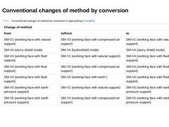
(Table: Conventional changes of method by conversion in pipe jacking [Tunnel01]) |
|

|

|

|

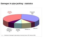
In jacking processes, extensive and irreparable damages are frequently observed, which is due to irregularities of the subsoil. Although extensive subsoil investigations can reduce the subsoil risk, failures and damages cannot be completely excluded. These are the consequences of damages during pipe jacking: -
Insufficient quality of the construction execution
-
Delay
-
High costs
-
Environmental impacts
|
|
|

(Image: Distribution of damages in pipe jacking in Germany (source: IFB, Hanover 1993)) |
|

|

|

|
|

This presentation is part of the series of presentations "Utility Tunnelling" and deals with the various types of shield machines, the removal of obstacles and possible errors in pipe jacking. |

|

Underground pipelines and utilities are predominantly installed by using the tradition open-cut (i.e., cut and fill) method: a trench is dug, the lines are installed by constructing proper embankment or sheeting or using a trench box, and the trench is filled afterwards. In the face of the numerous challenges (e.g., urbanization, densely populated areas) as well as growing environmental consciousness, it is important to consider trenchless technology … |
|

(Image: Manned techniques) (Image: Steerable techniques) Pipe jacking:
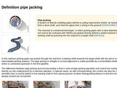
A system of directly installing pipes behind a cutting head and/or shield, by hydraulic jacking from a drive shaft, such that the pipes form a string in the ground [DINEN12889:2000].
The manned or unmanned technique, in which jacking pipes with a clear diameter ≥ 1200 mm (not to be confused with DN/ID) are jacked directly behind a shield machine from a starting shaft by pressing … |
|

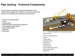
The components required for pipe jacking depend on the variant used to support the workface or convey excavated soil. However, the following key components are essential: -
Control and steering desk
-
Crane
-
Jacking pipes
-
Shield machine (tunnel boring machine)
-
Intermediate jacking station
-
Main jacking station
-
Abutment
-
Pipe brake
(Image: Schematic presentation of a pipe jacking - NEU) (Video: Pipe jacking in Bahrain) |

|

|
|

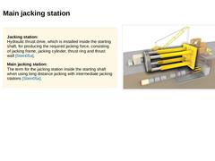
Jacking station:
Hydraulic thrust drive, which is installed inside the starting shaft, for producing the required jacking force, consisting of jacking frame, jacking cylinder, thrust ring and thrust wall [Stein05a]. Main jacking station:
The term for the jacking station inside the starting shaft when using long distance jacking with intermediate jacking stations [Stein05a]. (Image: Technical components in pipe jacking - main jacking station) |
|

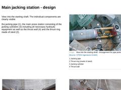
View into the starting shaft. The individual components are clearly visible: the jacking pipe (1), the main press station consisting of the jacking cylinders (3) including all necessary hydraulic equipment as well as the thrust wall (4) and the thrust ring made of steel (2). (Image: View into the starting shaft - Arrangement for pipe jacking) (Image: Damage to the jacking abutment due to inadequate dimensioning - Jacking forces cannot be absorbed by … |
|

|
(Image: Attention!)
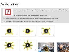
When choosing and/or arranging the jacking cylinders care must be taken of the following facts: -
the jacking cylinders used are identical in construction
-
the force resulting from the jacking force corresponds to the longitudinal axis of the pipe string
-
the jacking cylinders are arranged symmetrically with regards to the pipe cross-section
|
|
|
|
(Image: Use of two jacking cylinders combined with a steel pressure ring for four … |
|
|
|

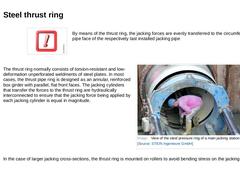
By means of the thrust ring, the jacking forces are evenly transferred to the circumference of the pipe face of the respectively last installed jacking pipe The thrust ring normally consists of torsion-resistant and low-deformation unperforated weldments of steel plates. In most cases, the pipe ring is designed as an annular, reinforced box girder with parallel, flat front faces. The jacking cylinders that transfer the forces to … |

|

|
|

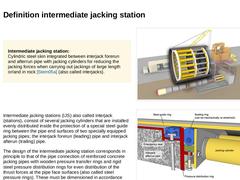
Intermediate jacking station:
Cylindric steel cylinder integrated between interjack forerun and afterrun pipe with jacking cylinders for reducing the jacking forces when carrying out jackings of large length or/and in rock [Stein05a] (also called interjacks). (Image: Technical components in pipe jacking - intermediate jacking station) Intermediate jacking stations (IJS) also called interjack (stations), consist of several jacking cylinders that are … |
|

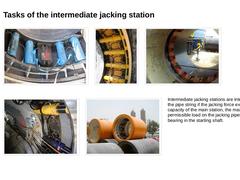
(Image: Intermediate jacking station - view of the jacking cylinders) (Image: Design and arrangement of intermediate jacking stations - Detail view of the jacking cylinders) (Image: Intermediate jacking station before installation of the cylinders) (Image: Built-in and activated cylinders of an intermediate jacking station) (Image: Intermediate jacking station before the installation in the pipeline tract)Intermediate jacking stations are integrated … |

|

Intermediate jacking stations are divided into two groups The recoverable IJS are installed from nominal size DN/ID 500 either immediately behind or at a short distance behind the jacking or shield machine and are pushed out of the target shaft with the pipe string or they are placed in the jacking string in such a way that the IJS is positioned exactly in an intermediate shaft after the end of the jacking and can be recovered … |
|

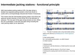
With intermediate jacking stations (IJS), the pipe string is divided into separate jacking sections, which are driven in cycles with a correspondingly reduced skin friction if necessary. This means that the intermediate jacking station only drives the advance section that lies in front of the IJS in the direction of advance. The rear part of the pipe string remains at rest. When the IJS is activated, it uses the rear pipe string including the main … |
|

(Video: Arrangement and development of the forces of intermediate jacking stations during pipe jacking) Video:Arrangement and development of the forces of intermediate jacking stations during pipe jacking [Image: S&P GmbH]. This interactive object is only visible online. |
|

|
(Image: Attention!)
The operation of the IJS is carried out from the steering desk. Only one hydraulic supply line is required for each station. |
For long jacking distances the single intermediate jacking stations are either supplied |
|

|
(Image: Attention!)
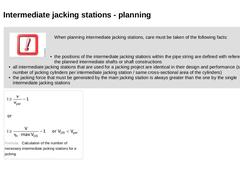
When planning intermediate jacking stations, care must be taken of the following facts: -
the positions of the intermediate jacking stations within the pipe string are defined with reference to the planned intermediate shafts or shaft constructions
-
all intermediate jacking stations that are used for a jacking project are identical in their design and performance (same number of jacking cylinders per intermediate jacking station / …
|
|

|

|
(Image: Pros and cons)
When using intermediate jacking stations, the following disadvantages must be expected: -
increase in costs due to the installation and the storage of all necessary system parts as well as the activation
-
reduction of the jacking performance
|
|