|
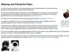
(Image: Securing the position of a liner of vitrified clay jacking pipes with reference to [FI-Stein96] [Image: S&P GmbH]) In order to create and adhere to the required gradient or the required position, the pipes should be aligned and fixed after being installed whenever possible. In non-man-accessible sections of the sewer to be rehabilitated, these measures are mainly limited to making the invert even before installing the pipes, the reduction of … |
|
|
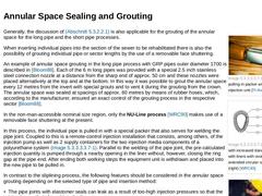
(Image: Special pulling-in packer with coupled injection unit [FI-Avent])
|
|
(Image: Regions with increased danger of buckling with liners with ovoid (left) and extended circular cross section (right) [WRC83])
|
|
(Image: Liner of short pipes with injection pipes placed on top for grouting the annular space and as spacers)
|
Generally, the discussion of Abschnitt 5.3.2.2.1 is also applicable for the grouting of the annular space for the long pipe and … |
|
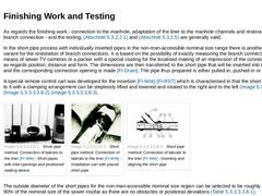
As regards the finishing work - connection to the manhole, adaptation of the liner to the manhole channels and restoration of the branch connection - and the testing, Abschnitt 5.3.2.2.1 and Abschnitt 5.3.2.5 are generally valid. In the short pipe process with individually inserted pipes in the non-man-accessible nominal size range there is another special variant for the restoration of branch connections. It is based on the possibility of exactly … |
|
Generally valid information on personnel requirements, equipment and capacities for the short and long pipe processes are not possible, as the method of insertion, for instance, the nominal sizes, pipe materials and pipe joints, the lengths of the sections of the sewer as well as the type and number of the laterals to be connected all influence them substantially. The basic equipment requirements for the different processes can be taken from the respective … |
|
Besides the advantages mentioned in Abschnitt 5.3.2.2.1 under points 8 to 11, the short pipe method offers the following additional advantages independent of the method of insertion: - Reduction of the earthworks and traffic disturbances due to the elimination of excavations;
- Fairly independent of the pipe material, nominal size and cross sectional shape;
- Simple reconnection of the laterals by installing correspondingly prepared individual pipes;
- Especially …
|
|
The following short pipe methods are understood to be special processes in which, by modifications, attempts are made to prevent one or other of the above-mentioned disadvantages.
In the Inter-Line Process, the path is taken of arranging the bearing function with PVC or PE short pipes with non-sealed lipped pipe joints and the tightness function by means of an outer double walled PVC hose between liner and sewer wall [FI-Haywa] [NN88a].
The PVC hose … |
|
In contrast to the sliplining process, in the long pipe and short pipe processes, self-supporting individual pipes are inserted discontinuously (in sequence) into the section of the sewer to be rehabilitated. The connection of the individual pipes to each other for the creation of the liner (in the following also called piping in order to distinguish it from the sliplining process), can either be carried out in the section of the sewer to be rehabilitated … |
|
(Image: Distribution of the lining processes) Lining with prefabricated pipes is characterised by the pulling, pushing or driving-in of pipes (also lining pipes) into the section of the sewer to be rehabilitated. The following processes are differentiated (Bild 5.3.2.2) : - Lining with a continuous pipe (sliplining process); (Abschnitt 5.3.2.2.1)
- Lining with long pipes (long pipe process); (Abschnitt 5.3.2.2.2)
- Lining with short pipes (short pipe process) (…
|
|
The in situ spiral lining process requires the following equipment that can be accommodated in a trailer: - Winding machine with exchangeable winding forms;
- Hydraulic pump for the drive;
- Holder for the plastics profile pipe roller;
- Light lifting equipment;
- Equipment for leaktightness testing;
- Equipment for annular space grouting;
- Cutting, boring or milling tools for the connections (robot).
An additional folding tent with opening sides permits the covering … |
|
The advantages of the in-situ spiral lining system are as stated in numbers 7, 8, 9 and 11 of the conventional sliplining process mentioned in Abschnitt 5.3.2.2.1 and the disadvantages are as stated in numbers 2 to 8. The system is very adaptable because of the numerous profiles and materials, as well as its machine and process techniques. As this is a mechanical process, the time required for the actual lining is very short; also the investment effort … |
|
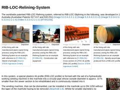
The worldwide patented RIB-LOC-Relining system, referred to RIB-LOC-Sliplining in the following, was developed in 1984 in Australia (Australian Patents 527 417 and 530 251) (Bild 5.3.2.3.1.1) (Bild 5.3.2.3.1.1) (Bild 5.3.2.3.1.1) (Bild 5.3.2.3.1.1) (Abschnitt 5.3.2.3.1.1) [ATVA115b]. | (Image: Depiction of the lining with site manufactured pipes (spiral lining process) using the RIB-LOC-Relining-System as an example with reference to [FI-RIBLOb] - … |
|
|
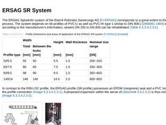
The ERSAG Spiralrohr system of the Eternit Rohrnetz-Sanierungs AG [FI-ERSAG] corresponds to a great extent to the RIB-LOC process. The system depends on rib profiles of PVC-U as well as PVC-HI type 1 similar to DIN 8061 [DIN8061:1984] with which, according to the manufacturer's information, sewers DN 200 to DN 800 can be rehabilitated (Tabelle 5.3.2.3.1.2). (Table: Profile dimensions and areas of application of the ERSAG-SR system [FI-ERSAG] [Kelda88]) |
|
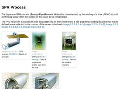
The Japanese SPR process (Sewage Pipe Renewal Method) is characterised by the winding of a liner of PVC rib profiles with steel reinforcing strips within the section of the sewer to be rehabilitated. The PVC rib profile is wound off a roll and added via an entry manhole to a self-propelling winding machine that moves along an defined space adapted to the contour of the sewer to be lined (Bild 5.3.2.3.1.3) (Bild 5.3.2.3.1.3) (Bild 5.3.2.3.1.3) (Bild … |
|
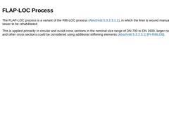
The FLAP-LOC process is a variant of the RIB-LOC process (Abschnitt 5.3.2.3.1.1), in which the liner is wound manually into the sewer to be rehabilitated. This is applied primarily in circular and ovoid cross sections in the nominal size range of DN 700 to DN 1600, larger nominal sizes and other cross sections could be considered using additional stiffening elements (Abschnitt 5.3.2.3.1) [FI-RIBLOb]. |
|
The following belong to the lining processes with site manufactured pipes with annular spaces: - RIB-LOC-Relining system (Abschnitt 5.3.2.3.1.1) ;
- ERSAG Spiralrohr system (spiral pipe system) (Abschnitt 5.3.2.3.1.2) ;
- SPR technology (Abschnitt 5.3.2.3.1.3) ; and
- FLAP-LOC process (Abschnitt 5.3.2.3.1.4).
|
|
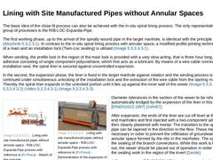
The basic idea of the close-fit process can also be achieved with the in-situ spiral lining process. The only representative of this group of processes is the RIB-LOC-Expanda-Pipe. The first working phase, up to the arrival of the spirally wound pipe in the target manhole, is identical with the principle described in Abschnitt 5.3.2.3.1. In contrast to the in-situ spiral lining process with annular space, a modified profile jointing technique consisting … |
|
Characteristic of this group of processes is the site manufactured of a self-carrying or statically stable liner (Abschnitt 5.3.2.1) either immediately before the insertion into the section of the sewer to be rehabilitated or within the same. The liner so produced is immediately load carrying and functional. One distinguishes between the following groups of processes (Bild 5.3.2) : - Lining with site manufactured pipes with annular space; and
- Lining …
|
|
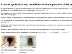
As regards the areas of application and conditions for the application of the Insituform process, reference should be made to the discussion on the sliplining process with annular space in Abschnitt 5.3.2.2.1. In a deviation from this, according to the manufacturer, the region of application ranges from DN 100 to 2600 for inversion lengths of 600 m and more [Dilg91]. Inversion lengths are distances that can be rehabilitated in one working step (at … |
|
The Insituform process is carried out from the existing manholes. After sealing off the laterals and shutting down the sector to be rehabilitated (Abschnitt 5.5), it is thoroughly cleaned, e.g. with a high pressure process. Projecting sewers, roots, deposits and other flow obstacles must be removed. Depending on the type of damage, e.g. projecting or recessed nozzles, a preparatory treatment with a milling and/or trowel robot should be carried out … |
|
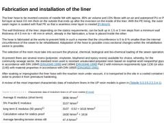
The liner hose to be inverted consists of needle felt with approx. 85% air volume and 15% fibres with an air and waterproof PU or PE foil layer at least 0.6 mm thick on the outside that ends up after the inversion on the inside of the liner. With the PE lining, the outer seam region is soaked with fluid PE so that a seamless inner layer is created [FI-Broch].
The wall thickness of the liner, depending on the statics requirements, can be built up … |
|
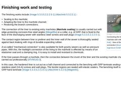
(Image: Connecting the liner into the entry manhole with reference to [FI-Insit] - View of the manhole connection [Image: S&P GmbH]) The finishing works include (Bild 5.3.2.4.1) (Abschnitt 5.3.2.2.1) : - Sealing to the manhole;
- Adapting the liner to the manhole channel;
- Restoring the branch connections.
The connection of the liner to existing entry manholes (Manhole sealing) is usually carried out with edge-protecting corrosion-free steel angles [Miege89a] … |
|
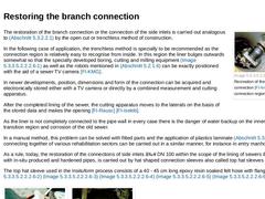
(Image: Recreation of the branch connection [FI-Insit] - Opening the connection region of the lateral) The restoration of the branch connection or the connection of the side inlets is carried out analogous to Abschnitt 5.3.2.2.1 by the open cut or trenchless method of construction. In the following case of application, the trenchless method is specially to be recommended as the connection region is relatively easy to recognise from inside. In this … |
|
In the course of the relining measures, in accordance with [LB310] and in similarity to [Gütes96], the following measures for testing and own supervision must be carried out and documented: - Control and documentation of the cleaning, inspection, measuring and calibrating of the section of the sewer to be rehabilitated.
- Entry control of the liner hose with information of manufacturer, goods supply of resins, goods supply of carrier material, resin recipes, …
|
|
The time taken for a rehabilitation process is relatively independent of the inversion length. It takes between 1 and 2 working days per rehabilitation sector or length irrespective whether the length is 50 m or 500 m. Work is always carried out in day and night shifts. Pauses are arranged irregularly and are dependent on the progress of the work. The personnel requirement for the work is 3 - 5 persons depending on the dimension and length of hose. |
|
The advantages of the Insituform process are: - Short installation time (approx. 1 - 2 days per rehabilitation sector).
- The work can be carried out from the available entry manholes; in this case no finishing work is necessary.
- Independent of the pipe material and also relatively of the cross sectional shape.
- Applicable normally in the non-man-accessible region from DN 100 (for corrosion protection measures also to DN 2600) and sections of the sewer …
|