|

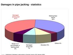
| (Image: Distribution of damages in pipe jacking in Germany (source: IFB, Hanover 1993))
|
|
|
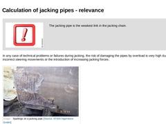
| (Image: Attention!) The jacking pipe is the weakest link in the jacking chain. | | In any case of technical problems or failures during jacking, the risk of damaging the pipes by overload is very high due to incorrect steering movements or the introduction of increasing jacking forces. | | (Image: Spallings on a jacking pipe) |
|
|
|
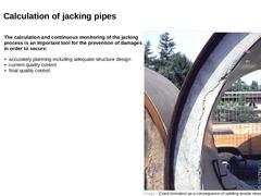
The calculation and continuous monitoring of the jacking process is an important tool for the prevention of damages in order to secure: - accurately planning including adequate structure design
- current quality control
- final quality control
| (Image: Crack formation as a consequence of splitting tensile stresses due to unbalanced load introduction into the pipe faces)
|
|

|
|
|
|
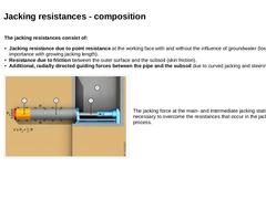
The jacking resistances consist of: - Jacking resistance due to point resistance at the working face with and without the influence of groundwater (loses importance with growing jacking length).
- Resistance due to friction between the outer surface and the subsoil (skin friction).
- Additional, radially directed guiding forces between the pipe and the subsoil due to curved jacking and steering errors.
| | (Image: Penetration resistance and jacking force)
|
|
|
|
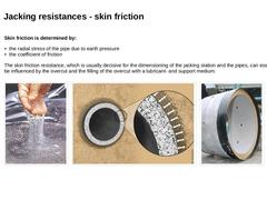
Skin friction is determined by: - the radial stress of the pipe due to earth pressure
- the coefficient of friction
The skin friction resistance, which is usually decisive for the dimensioning of the jacking station and the pipes, can essentially be influenced by the overcut and the filling of the overcut with a lubricant- and support medium. | |
(Image: T.B.K. system [FI-TBKa] - Injection medium (Polymer drilling fluid consisting of polymer and water))
|
|
|
|
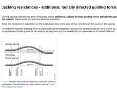
| Curved jackings and steering errors frequently induce additional, radially directed guiding forces between the pipe and the subsoil. These forces increase the frictional resistance. Since this resistance is dependent on the longitudinal force in the pipe string, it increase in the course of the jacking. The effect of repeated steering errors is particularly disadvantageous, because the single resistances do not sum up, but lead to an disproportionate … |
|

|
(Video: Operating forces during pipe jacking) |
|
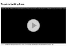
(Video: Arrangement and development of the forces of intermediate jacking stations during pipe jacking) |
|
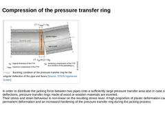
| (Image: Buckling condition of the pressure transfer ring for the angular deflection of the pipe end faces) | | In order to distribute the jacking force between two pipes onto a sufficiently large pressure transfer area also in case of angular deflections, pressure transfer rings made of wood or wooden materials are inserted.
Their stress and strain behaviour is non-linear on the resulting stress level. A high proportion of plastic deformation causes … |
|
|
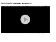
(Video: Calculation in the direction of the pipe axis: deformation at the pressure transfer ring during pipe jacking) |
|
|
|
|
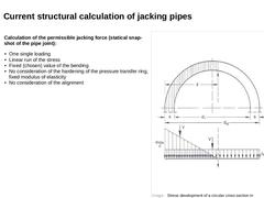
Calculation of the permissible jacking force (statical snap-shot of the pipe joint): - One single loading
- Linear run of the stress
- Fixed (chosen) value of the bending
- No consideration of the hardening of the pressure transfer ring, fixed modulus of elasticity
- No consideration of the alignment
| (Image: Stress development of a circular cross section in dependence on the proportion z/da [ATVA161])
|
|
|
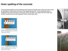
| The presented problem of the hardening of the pressure transfer ring is often the main cause for damages or destructions that occur during jacking process. This is frequently due to spallings at the outer end faces of the pipe, which are often not visible from the inside and remain unnoticed at the final inspection of the construction work. | | (Image: Example of a reinforced concrete spalling of exceeding the concrete compressive strength at the pipe … |
|
|

|
| (Image: CoJack - Logo)
|
Computing and Controlling Pipe-Jacking | |
The calculation program "CoJack" developed by Prof. Dr.-Ing. Stein & Partner GmbH serves as a practical and powerfull instrument to increase the safety and economic effiency of pipe jackings. |
|
|
|
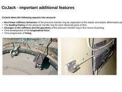
CoJack takes the following aspects into account: - Non-linear stiffness behaviour of the pressure transfer ring by separation of the elastic and plastic deformation parts.
- The loading history of the pressure transfer ring for each observed point of time.
- Changes in the stiffness and the geometry of the pressure transfer ring in the course of jacking.
- Time development of the longitudinal force.
- Time progression of lining.
| |
(Image: Electronic measuring … |
|
|
|
|
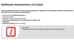
Important additional input of CoJack (input parameters in addition to the calculation methods currently taken into consideration are
presented in bold letters): - pipe geometry including tolerances
- concrete strength
- geometry of the pressure transfer ring
- real stress-strain behaviour of the pressure transfer ring
- alignment
- incorrect steering within the jacking
| | (Image: Attention!)
Conclusion:
Simulative jacking along the alignment with the required … |
|
|
|
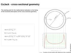
The starting point for the mathematical realisation is the listing of the functional description of the cross-sectional geometry. | (Image: Function of cross section with reference to the z-coordinates of the calculation example)
| | (Image: Formula for calculating the load transfer ring width of the cross section B(z) for a circular cross section)
|
|
|
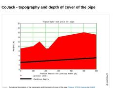
| (Image: Functional description of the topography and the depth of cover of the pipe)
|
|
|
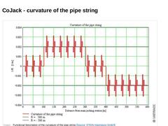
| (Image: Functional description of the curvature of the pipe string)
|
|
|
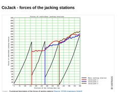
| (Image: Functional description of the forces of jacking stations)
|
|
|
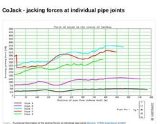
| (Image: Functional description of the jacking forces at individual pipe joints)
|
|
|
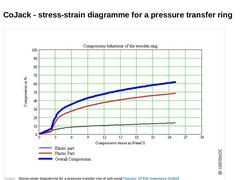
| (Image: Stress-strain diagramme for a pressure transfer ring of soft wood)
|
|
|
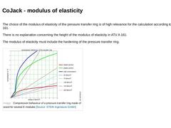
| The choice of the modulus of elasticity of the pressure transfer ring is of high relevance for the calculation according to ATV A 161. There is no explanation concerning the height of the modulus of elasticity in ATV A 161. The modulus of elasticity must include the hardening of the pressure transfer ring. | | (Image: Compression behaviour of a pressure transfer ring made of wood for several E-modules) |
|

|
(Video: Calculation in the direction of the pipe axis: stress distribution at the pressure transfer ring during pipe jacking) |
