|
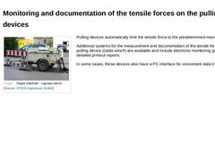
(Image: Target manhole - capstan winch) Pulling devices automatically limit the tensile force to the predetermined maximum value. Additional systems for the measurement and documentation of the tensile forces on the pulling device (cable winch) are available and include electronic monitoring gauges and detailed printout reports. In some cases, these devices also have a PC interface for convenient data transfer. |
|
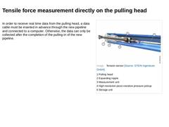
In order to receive real time data from the pulling head, a data cable must be inserted in advance through the new pipeline and connected to a computer. Otherwise, the data can only be collected after the completion of the pulling-in of the new pipeline. |
|
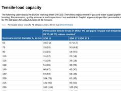
The following table shows the DVGW working sheet GW 323 (Trenchless replacement of gas and water supply pipelines with pipe bursting; Requirements, quality assurance and inspections / not available in English at present) specified permissible tensile forces for PE 100 pipes for a load duration of 30 minutes. (Table: Permissible tensile forces for PE 100 pipes under a 30 min load [DVGWGW323]) |
|
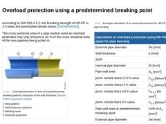
According to GW 323-4.3.2, the breaking strength of HD-PE is 2.5 times the permissible tensile stress [DVGWGW323]. The cross sectional area of a pipe section used as overload protection may only amount to 40 % of the cross sectional area of the new pipeline being pulled in. (Image: Overload protection in form of a predetermined breaking point by reduction of the wall thickness) (Table: Example calculation of an overload protection for HD-PE 100 used … |
|
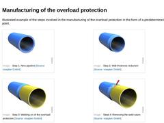
Illustrated example of the steps involved in the manufacturing of the overload protection in the form of a predetermined breaking point. (Image: Step 1: New pipeline) (Image: Step 2: Wall thickness reduction) (Image: Step 3: Welding on of the overload protection) (Image: Stept 4: Removing the weld seam) |
|
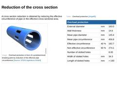
A cross section reduction is obtained by reducing the effective circumference of pipe or the effective cross-sectional area. (Image: Overload protection in form of a predetermined breaking point by reduction of the effective pipe circumference) (Table: Overload protection) |
|
|

|
Congratulations! You have successfully finished this lesson. Next you will have the opportunity to review the newly acquired knowledge with an interactive questionnaire. You can of course still navigate back to any point in the lessons if you wish to review a specific point or subject. Stay curious! |
|
This module is devoted to the pipe bursting as a special method of the replacement of pipelines. In addition, the module looks at the effects that pipe bursting has on the pipeline itself as well as its surrounding environment. Upon the successful completion of this module, you will be able to: - identify the effects of pipe bursting on the surrounding environment,
- calculate the required minimum distances to the adjacent utilities and structures, and
- identify methods of tensile force control and restriction
|

|
Replacement: (Definition as per [DINEN752-4])
Construction of a new drain or sewer, on or off the line of an existing drain or sewer, the function of the new drain or sewer incorporating that of the old one. The replacement is always carried out at least in section lengths of the sewer using: Open Cut Method (Image: Replacement of sewers using the open cut method) Semi Open Cut Method (Image: Replacement of a masonry sewer by the semi open cut method … |
|
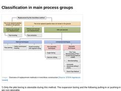
(Image: Overview of replacement methods in trenchless construction) *) Only the pilot boring is steerable during this method. The expansion boring and the following pulling-in or pushing-in of the pipes are non-steerable. |
|
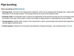
Terms according to [DWA-M143-15] -
Bursting head: Tool used in the replacement of pipelines, which can be equipped with breakage-rails, cutting rollers or similar - dependant on the old pipe material. The bursting head can be a part of the expander head.
-
Expander head: The expander head is used for the displacemet of the bursted host pipe into the surrounding subsoil, and also for the creation of an open cross section in which new smaller or larger …
|

|
|

|
European Standards: Drain and sewer systems outside buildings (2008-04) Trenchless construction and testing of drains and sewers (2000-03) German regulations: Rehabilitation of drain and sewer systems outside buildings, Part 15: Replacement of drains and sewer with pipe bursting / not available in english at the present |
|
DVGW Regulations: Trenchless replacement of gas- and water-supply pipelines using pipe bursting; Requirements, quality assurance and inspections / not available in english at present RSV-Data Sheets: Replacement of drains and sewers using pipe bursting; Requirements, quality assurance and inspections / not available in english
GSTT-Information: Trenchless methods of damage correction in non-accessable drains … |
|
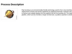
(Image: Replacement by trenchless method) Pipe bursting is an environmentally friendly technology used for the in situ trenchless replacement of drains and sewers (pipelines) by applying pneumatic, hydraulic and static energy to fracture and radially displace the host pipeline into the surrounding soil. The replacement pipeline, which can be of similar or larger nominal size, is pulled or pushed in simultaneously. |
|
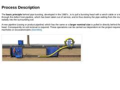
The basic principle behind pipe bursting, developed in the 1980's , is to pull a bursting head with a winch cable or a tension rod through the defect host pipeline, which has been taken out of service, and to thus destroy the pipe walling from the inside and force it radially into the surrounding soil. A new pipeline (casing or product pipeline) which has the same or a larger nominal size is pulled in directly behind the bursting head. Consequently … |
|
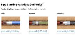
Pipe bursting forces are generated using the following three methods: |
|
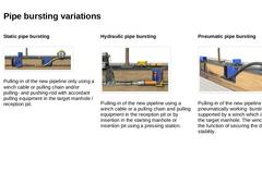
Static pipe bursting
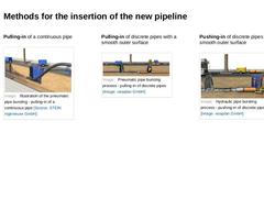
(Image: Illustration of the static pipe bursting - pulling-in of a continuous pipe) Pulling-in of the new pipeline only using a winch cable or pulling chain and/or pulling- and pushing-rod with accordant pulling equipment in the target manhole / reception pit. Hydraulic pipe bursting
(Image: Hydraulic pipe bursting process - pushing-in of discrete pipes) Pulling-in of the new pipeline using a winch cable or a pulling chain and pulling … |
|
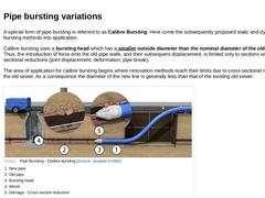
A special form of pipe bursting is referred to as Calibre Bursting. Here come the subsequently proposed static and dynamic pipe bursting methods into application. Calibre bursting uses a bursting head which has a smaller outside diameter than the nominal diameter of the old pipeline. Thus, the introduction of force onto the old pipe walls, and their subsequent displacement, is limited only to sections with cross-sectional reductions (joint displacement, … |
|
Pulling-in of a continuous pipe
(Image: Illustration of the pneumatic pipe bursting - pulling-in of a continuous pipe) Pulling-in of discrete pipes with a smooth outer surface (Image: Pneumatic pipe bursting process - pulling-in of discrete pipes) Pushing-in of discrete pipes with a smooth outer surface (Image: Hydraulic pipe bursting process - pushing-in of discrete pipes) |
|
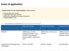
Requirements for the implementation of pipe bursting: -
Circular pipe cross section
-
Preferably brittle pipe materials
-
Sufficiently compacted host pipe embedment
-
Straight pipeline route
(Table: Areas of application for pipe bursting) |
|
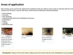
Pipe bursting can be used for the replacement of pipelines which are made of various types of materials (with the exception of pre-stressed and reinforced concrete with heavy reinforcement) exhibiting the following damages: -
Pipe breakage,
-
Corrosion,
-
Flow obstacles,
-
Unprofessionally performed rehabilitation processes,
-
Deformations,
-
Cracks,
-
Leakage,
-
Mechanical wear.
(Image: Longitudinal crack in the region of the pipe joint resulting positional … |
|
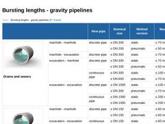
(Table: Bursting lengths - gravity pipelines [FI-Tracta]) |
|
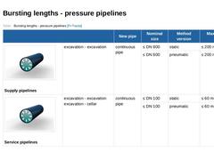
(Table: Bursting lengths - pressure pipelines [FI-Tracta]) |