|
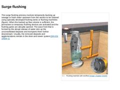
The surge flushing process involves temporarily backing up sewage or fresh water upstream from the section to be cleaned using specially developed flushing tanks or flushing manholes (figure). When the backed up flow volume is sufficient, the permanent or temporary flushing devices are activated and the flushing gates are abruptly opened. The wave front that is formed by the abrupt release of water stirs up the unconsolidated deposits and transports … |
|
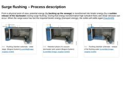
From a physical point of view, potential energy (by backing up the sewage) is transformed into kinetic energy (by a sudden release of the backwater) during surge flushing. During that energy transformation high turbulent flows and shear stresses can occur. When the surge wave has lost the required kinetic energy (transport energy), the solids will settle again [Haußm99]. (Image: Flushing chamber schematic - initial stage (Biogest-System)) |
|
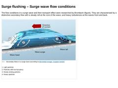
The flow conditions in a surge wave and their transport effect were researched by Brombach (figure). They are characterised by a distinctive secondary flow with a steady roll at the core of the wave, and heavy turbulences at the waves front and back. (Image: Secondary flows in a surge wave according to [Brombach]) |
|
Dettmar characterises the wave family created during surge flushing into so-called bed load and suspension waves [Dettm2005a]. -
Bed load waves are surge waves creating high wall shear stresses. Thus, these waves are able to mobilise coarse-particle and cohesive deposits and transport them as bed load and suspensions.
-
Suspension waves show less wall shear stresses. Therefore, they can only mobilise and transport fine-grained and suspended deposits. …
|

|
The efficiency of surge flushing is influenced by the following factors: -
Back up height and flushing water volume
-
Shape and dimensions of the cross-section
-
Alignment of the sewer section
-
Gradient of the sewer section to be flushed
-
Type and extent of the formed deposits
-
Condition of the pipe walls
-
Number and temporal sequence of the surge waves
-
Quantity of water in the flushing section (dry weather and wet weather water flow, u-bends, discharges, …
|

|
The effective range of surge flushing can be several hundred meters depending on the local conditions and the desired cleaning effect [Frühl1910]. Under favourable conditions, as in a straight section of the line with insignificant ponding, flushing lengths of more than 1,000 m can be achieved [Dettm2004a].
|

|
According to Haußmann, the following principles apply: -
A high frequency of surge waves (interval flushing) prevents the new formation of deposits more effectively than individual heavy surge waves.
-
Prior to flushing, the water level in the downstream water (ponding) should be rather low, so that the surge wave can directly act on the deposits and is not affected by the standing water.
-
In [ATV1995], a minimum filling depth of 4 to 5 cm is recommended, …
|

|
Currently, there are several different surge flushing devices used for surge flushing of drains and sewers as well as local drainage structures. According to [Dettm2004a], these devices are categorised into the following four groups based on their structure, technique, and equipment: -
Wastewater volume activated flushing system,
-
Flushing using a tipping bucket,
-
Flushing using a flushing chamber, and
-
Surge manhole flushing system.
|

|
When choosing the appropriate surge flushing device for a particular cleaning task, the following criteria is to be taken considered in addition to the hydraulic and structural limiting conditions [Dettm2004a]: -
Type and dimensions of sewer,
-
Location of section to be cleaned within the sewer network,
-
Elevation of the section to be cleaned relative to the system, and
-
Access to the infrastructure (e.g. electricity supply to provide power)
|
|
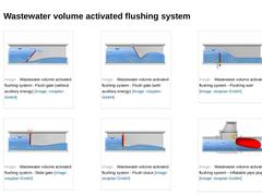
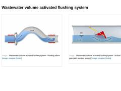
Wastewater volume activated flushing systems consists of sealing devices that are especially arranged perpendicularly to the flow direction in order to backup the wastewater upstream of the section to be cleaned. Depending on the type of sealing device, the sewer cross section is blocked entirely or partly. The flush gate, arched flush gate, flushing weir, flush sluice, inflatable pipe plug and rotating elbow are among the wastewater volume activated … |
|
(Image: Wastewater volume activated flushing system - Flush gate (without auxiliary energy)) (Image: Wastewater volume activated flushing system - Flush gate (with auxiliary energy)) (Image: Wastewater volume activated flushing system - Flushing weir) (Image: Wastewater volume activated flushing system - Slide gate) (Image: Wastewater volume activated flushing system - Flush sluice) (Image: Wastewater volume activated flushing system - Inflatable pipe … |
|
(Image: Wastewater volume activated flushing system - Rotating elbow) (Image: Wastewater volume activated flushing system - Arched flush gate (with auxiliary energy)) |
|
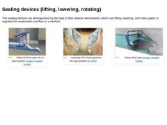
The sealing devices are distinguished by the type of flow release mechanisms which use lifting, lowering, and rotary gates to regulate the wastewater overflow or underflow. (Image: Lifting the flush gate into an open position) (Image: Lowering of the flush gate into the open position) (Image: Rotary flush gate) |
|
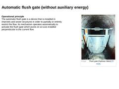
Operational principle
The automatic flush gate is a device that is installed in channels and sewer structures in order to partially or entirely restrict the flow. Its mechanism operates automatically to activate the flush gate which pivots on an axis installed perpendicular to the current flow. (Image: Flush gate (Hydrass Valve)) |
|
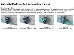
Operational principle
The energy required for tipping the gate is generated from the sewer flow itself. Owing to the operating principle, there is no need for a special system for measurement and control, which minimise maintenance. The following illustrations depict the operational phases of the flush gate as effected by the hydrostatic pressure above (MO), and below (MU) of the rotational axis. (Image: Automatic flush gate (without auxiliary energy) … |
|
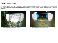
The Hydrass Valve or “Berlin flap“ is composed of a plate that is mounted to a metal frame, which is adjusted to the sewer profile. The length of the rotation axis can be freely selected. According to [Loren1998], it should be at the same level as the dry weather water flow. (Image: Flush gate DN 1600, closed position) (Image: Flush gate DN 1600, open position) |
|
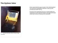
(Image: Automatic flush gate (without auxiliary energy)) At low water levels the gate remains in the vertical position. This causes the wastewater upstream to back up and increases the water level h0. So long as the wastewater pressure is greater bellow the rotational axis of the gate than above it, the gate will remain closed and continue to back up the wastewater. |
|
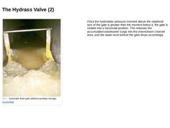
(Image: Automatic flush gate (without auxiliary energy)) Once the hydrostatic pressure moment above the rotational axis of the gate is greater than the moment below it, the gate is rotated into a horizontal position. This releases the accumulated wastewater surge into the downstream channel area, and the water level behind the gate drops accordingly. |
|
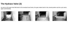
As soon as the water level falls back to the standard local levels, the gate rotates back to the closed position and the cycle starts again automatically. (Image: Automatic flush gate (without auxiliary energy) - Surge wave generation) (Image: Automatic flush gate (without auxiliary energy) - Surge wave generation) (Image: Automatic flush gate (without auxiliary energy) - Surge wave generation) (Image: Automatic flush gate (without auxiliary energy) - … |
|
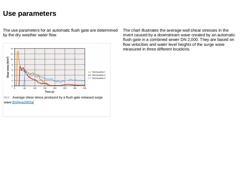
The use parameters for an automatic flush gate are determined by the dry weather water flow. (Image: Average shear stress produced by a flush gate released surge wave)
The chart illustrates the average wall shear stresses in the invert caused by a downstream wave created by an automatic flush gate in a combined sewer DN 2,000. They are based on flow velocities and water level heights of the surge wave measured in three different locations. |

|
|
|
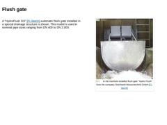
A "HydroFlush GS" [FI-Steinh] automatic flush gate installed in a special drainage structure is shown. This model is used in nominal pipe sizes ranging from DN 400 to DN 2,000.
(Image: In the manhole installed flush gate "Hydro Flush" from the company Steinhardt Wassertechnik GmbH) |
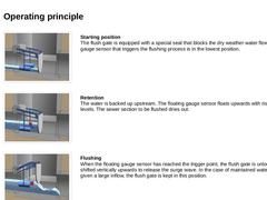
|
(Image: Automatic flush gate (without auxiliary energy) - Starting position) Starting position
The flush gate is equipped with a special seal that blocks the dry weather water flow. The floating gauge sensor that triggers the flushing process is in the lowest position. (Image: Automatic flush gate (without auxiliary energy) - Retention) Retention
The water is backed up upstream. The floating gauge sensor floats upwards with rising water levels. The … |
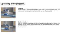
|
(Image: Automatic flush gate (without auxiliary energy) - Lowering) Lowering
The flush gate is lowered with the falling water level up to a given locking point, so that the trailing water containing the mobilised solids can run off unimpeded. (Image: Automatic flush gate (without auxiliary energy) - Starting position) Starting position
After the retention area is drained, the float gauge sensor activates the closing of the flush gate. It moves into the … |

|
|