|
Decentralised solid retention is defined to include “measures for the retention of solids in the place of their formation before the sewage is fed into the sewage system”. In the opinion of many authors ( [Grott1991] [Giesl1997] [Kraut2000] [Stotz1998] [Somme2004a] [Somme2004] [Fraen2005] [Hilli2005] [SteinR05]) the runoff entering the sewage system from the surface via catch basins is the main source of mineral solids resulting in the formation of … |
|
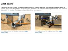
Catch basins are used to collect and direct rainwater delivered by drainage swales and road gutters into combined sewers or separate storm sewers through lateral sewer connections. In addition to the collection and drainage of rainwater, catch basins are also used for the retention of solids and ventilation of combined sewer systems. (Image: Road cross section with a combined sewer system) (Image: Road cross section with a separated sewer system) |
|
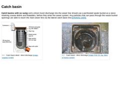
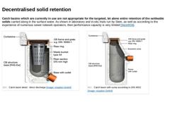
Catch basins with no sump and a direct invert discharge into the sewer line should use a perforated waste bucket as a sieve retaining coarse debris and floatables, before they enter the sewer system. Any particles that can pass through the waste bucket openings are able to reach the main sewer line via the lateral catch basin line [DIN4052:2006]. (Image: Catchbasin detail - direct discharge) (Image: Catch basin - direct discharge) |
|
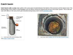
Catch basins with a sump retain solids in the sump space located between the bottom of the structure and the lateral invert. The disadvantage of this system is that floatables such as leaves cannot be retained and end up in the sewer system. This is also the case with debris in the sump which gets disturbed during heavy storm events [DIN4052:2006]. (Image: Catch basin with sump) (Image: Catch basin debris) |
|
|
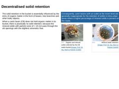
The solid retention in the bucket is essentially influenced by the entry of organic matter in the form of leaves, tree branches and other bulky objects. When a catch basin (CB) does not hold organic matter in its bucket, there is practically no solid retention, because the mineral solids with particle sizes of < 16 mm pass through the slit openings with the slightest volumetric flow. |
Consequently, catch basins with an outlet at the invert level … |
|
|
Catch basins which are currently in use are not appropriate for the targeted, let alone entire retention of the settleable solids carried along in the surface water. As shown in laboratory and in-situ trials run by Stein, as well as according to the experience of numerous sewer network operators, their performance capacity is very limited [SteinR08]. (Image: Catchbasin detail - direct discharge) (Image: Catch basin with sump) |
|
Owing to this knowledge, many authors ( [SteinR08] [Artie1988] [Sande1994] [Bromb1993] [Grott1991] [Giesl1997] [Kraut2000] [Stotz1998] [Somme2004a] [Somme2004] [Fraen2005] [Hilli2005]) recommend the replacement of conventional catch basins with new structures that have an improved cleaning function or solid retention. This improved separation of solids from the flow reduces operational requirements by increasing cleaning intervals. |
|
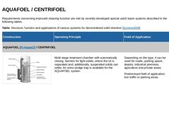
Requirements concerning improved cleaning function are met by recently developed special catch basin systems described in the following tables. Table: Structure, function and applications of various systems for decentralized solid retention [Somme2009] |
Construction |
Operating Principle |
Field of Application |
|
AQUAFOEL [FI-AquaCl] / CENTRIFOEL |
|
(Image: Decentralized solids retention catch basin with improved solids retention) |
Multi-stage treatment … |
|
|
Table: Structure, function and applications of various systems for decentralized solid retention [Somme2009] (Continued) |
Construction |
Operating Principle |
Field of Application |
|
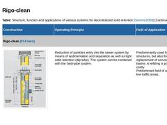
Rigo-clean [FI-Fraen] |
|
(Image: Rigo-clean) |
Reduction of particles entry into the sewer system by means of sedimentation and separation as well as light solid retention (dip tube). The system can be combined with the Sedi-pipe system. |
Predominantly used for newly built … |
|
|
Table: Structure, function and applications of various systems for decentralized solid retention [Somme2009] (Continued) |
Construction |
Operating Principle |
Field of Application |
|
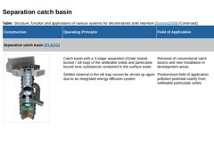
Separation catch basin [FI-ACO] |
|
(Image: Separation catch basin) |
Catch basin with a 3-stage separation (Grate /waste bucket / silt trap) of the settleable solids and particulate bound toxic substances contained in the surface water. Settled material in the silt trap cannot … |
|
|
Table: Structure, function and applications of various systems for decentralized solid retention [Somme2009] (Continued) |
Construction |
Operating Principle |
Field of Application |
|
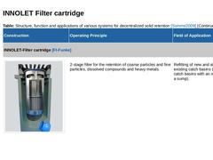
INNOLET-Filter cartridge [FI-Funke] |
|
(Image: INNOLET Filter insert) |
2-stage filter for the retention of coarse particles and fine particles, dissolved compounds and heavy metals. |
Refitting of new and already existing catch basins (conventional catch basins with an invert … |
|
|
Table: Structure, function and applications of various systems for decentralized solid retention [Somme2009] (Continued) |
Construction |
Operating Principle |
Field of Application |
|
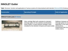
INNOLET-Gutter grate [FI-Sieke] |
|
(Image: Decentralized solids retention) |
Filter cartridge filled with substrate for standard drainage gutters for fine particles and dissolved heavy metals. A coarse particle cartridge is also included for the retention of leaves and coarse … |
|
|
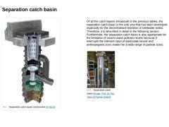
(Image: Separation catch basin) Of all the catch basins introduced in the previous tables, the separation catch basin is the only one that has been developed especially for the decentralised retention of settleable solids. Therefore, it is described in detail in the following section.
Furthermore, the separation catch basin is also appropriate for the limitation of severe water pollution levels because it interrupts the relevant input of particulate … |
|
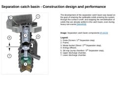
(Image: Separation catch basin components) The development of the separation catch basin was based on the goal of retaining the settleable solids entering the system through the surface runoff, and stopping the remobilisation of solids that are already settled in the catch basin, even during heavy rain events [SteinR08]. Image: Separation catch basin components [FI-ACO] Legend:
1. Grate (Screen / 1st Separation step)
2. Frame,
3. Waste bucket (Sieve / … |
|
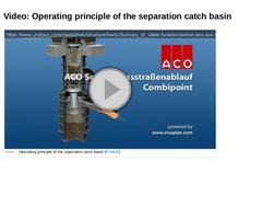
(Video: Video:Operating principle of the separation catch basin) |
|
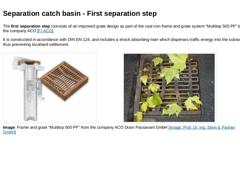
The first separation step iconsists of an improved grate design as part of the cast iron frame and grate system “Multitop 500 PF” by the company ACO [FI-ACO]. It is constructed in accordance with DIN EN 124, and includes a shock absorbing riser which disperses traffic energy into the subsoil thus preventing localised settlement. (Image: Separation catch basin - frame and grate) (Image: Catch basin grate) : Frame and grate “Multitop 500 PF” from … |
|
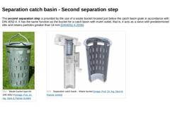
The second separation step is provided by the use of a waste bucket located just below the catch basin grate in accordance with DIN 4052-4. It has the same function as the bucket for a catch basin with invert outlet, that is, it acts as a sieve with predetermined slits and retains particles greater than 16 mm [DIN4052-4:2006]. (Image: Waste bucket type A4 DIN 4052-4) (Image: Separation catch basin - waste bucket) |
|
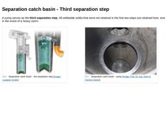
A sump serves as the third separation step. All settleable solids that were not retained in the first two steps are retained here, even in the event of a heavy storm. (Image: Separation catch basin - 3rd separation step) (Image: Separation catch basin - sump) |
|
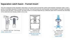
The core component of the separation catch basin is an insert used to funnel the surface water between separation steps 2 and 3 and for a controlled reduction of energy in the silt trap. The insert funnels the incoming water and discharges it through a downpipe into the sump (silt trap). In the process, the water stream is circularly dispersed by a deflection plate which minimises the disturbance of the solids that have already settled in the sump. |
|
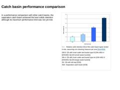
In a performance comparison with other catch basins, the separation catch basin achieved the best solids retention although its maximum performance limit was not yet met. (Image: Relative solid retention [%] of the catch basin types tested in-situ, assuming one cleaning measure per year) |
|
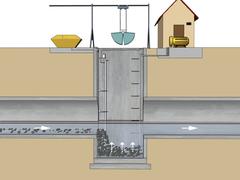
This module deals with the topics of semi-centralized and decentralized sedimentation of solids. One focus is on decentralized sedimentation using road catch basins. The different designs and modes of operation of these structures are explained and their performance is demonstrated. After completing this module, you will have knowledge regarding: - constructive measures to prevent sedimentation;
- procedural principles of these constructive measures.
|
|
Pressure lines, that is “lines for the transport of sewage under pressure” are cleaned using methods. |
|
Physical methods aim at an increase of the sewage flow velocity for cleaning purposes by the addition of pressurised air. Flushing is performed two to four times a day, or more often if required, by blowing air into the pressure pipe system. Thus, the flow cross section in the pressure pipelines is decreased. Due to the increased sewage velocity, deposits are stirred up and transported further downstream. |
|
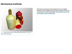
(Image: Pipe scrapers used for cleaning purposes) Mechanical cleaning of pressurised lines uses available methods and technology from the gas and water sectors, for example, the so.called "pipe pigs" [Führb1980] [Arsco1979] [Jenki1968] [Jordan] [Walsk1984]. |
|
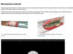
The pipe pig closes the cross section of the line and is either forced through the line to be cleaned by the sewer flow, or through the addition of pressure (water or pressurised air). Inserting and removing the pipe pig is performed using locks (pig traps). This procedure requires fittings, such as ball valves and isolating valves that can entirely open and close the cross section of the pipe. (Image: Operational principle of a pipe pig) |